Designers compose modular machine tools from standard components and specialized parts, enabling them to process specific components or similar parts. They have simpler structures, higher efficiency, and are ideal for mass single-process machining.
Modular machine tools offer stable, versatile machining and reusable components, making them more suitable than dedicated machines.
Fixtures must provide precise clamping and force to prevent deformation and ensure accurate positioning.
In machine tool production, selecting appropriate fixtures ensures production efficiency and reduces labor intensity.
Modular fixtures offer good flexibility and rigidity, with removable and reconfigurable components. This design employs a universal structural approach.
Housing Machining Process
Before detailing the specific machining analysis, it is essential to understand the functional role and performance requirements of the transmission housing within the tractor’s rear assembly.
As a structural component that supports transmission loads, aligns shafts, and ensures stable power delivery, the housing must meet strict geometric and dimensional standards.
Therefore, the following section analyzes the housing’s process characteristics, precision demands, and machining challenges, providing the foundation for subsequent process design and optimization.
Housing Process Analysis
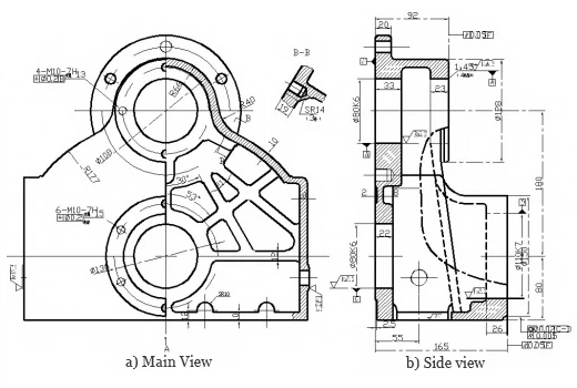
The workpiece is a thin-walled end transmission housing in the tractor’s rear assembly, supporting transmission forces.
Bearings at both drive shaft ends require high concentricity and precision, as errors can affect tractor operation and shorten bearing and shaft life.
The transmission housing features four machined planes: the opening plane and planes A, B, and C.
Machining requires multiple transverse and threaded holes on planes A, B, C, and the opening, with high precision needed for surfaces and holes.

Flatness requirements. The opening plane and end faces A, B, C are primary surfaces, with the opening plane needing 0.05 mm perpendicularity to them.
Hole system specifications. Many vertically arranged holes require coaxial systems with positional tolerances ≤0.2 mm.
The rear end face has two Φ80 mm holes (depths 33 mm and 22 mm) with 0.02 mm coaxiality; the front end has a Φ80 mm hole 23 mm deep.
Positioning accuracy between hole systems and planes. The main planes are the front/rear end faces and opening plane, with the Φ110 mm front face requiring 0.04 mm parallelism to the rear face.
The front and rear end faces must be perpendicular to the transverse hole system axis with a perpendicularity tolerance of 0.05 mm;
Surface roughness. The opening plane may serve as a precision reference surface. The roughness of the primary machined planes and bored holes is 3.2.
Structural Manufacturability
Engineers uniformly distribute the threaded holes within the plane to ensure good structural manufacturability.
Two-sided boring reduces the length of the boring bar; the opening plane functions as a precision reference, facilitating production;
Operators can machine the uniformly distributed Φ8 mm threaded holes simultaneously to minimize tool changes.
Benchmark Selection Principles
Engineers should use precision benchmarks to ensure benchmark coincidence, avoiding errors from non-coincidence, especially during final finishing.
Benchmark Unification: A single benchmark ensures accuracy, prevents errors, and simplifies process design.
Mutual Benchmarking: Two surfaces can act as mutual benchmarks to maintain positional accuracy in repeated machining.
Engineers can select the surface itself as the precision reference when certain finished surfaces require small, uniform allowances.
This principle also applies to operations using fixed-diameter drills, such as floating drill jig boring and reaming.
Overall Design of Combination Machine Tools
Based on the machining requirements and structural characteristics of the transmission housing, the overall design of the combination machine tool must ensure high precision, rigidity, and production efficiency. The design process focuses on selecting an appropriate machine configuration, optimizing structural layout, and matching the machine’s performance with the part’s dimensional and tolerance requirements. The following section discusses the selection principles and configuration types of modular combination machine tools to establish a foundation for subsequent detailed design.
Selection of Modular Machine Tool Configuration Types
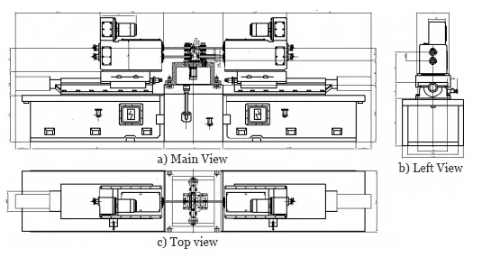
The machine tool primarily consists of a spindle housing, base, motor, electrical equipment, slide, and cutting tools.
The spindle drives the tools, the base supports components, and the slide secures the fixture with precise longitudinal feed.
Configuration schemes affect machining by defining component and controller arrangements.
For Φ80 mm and Φ110 mm holes, a horizontal machine ensures easy setup, stability, and efficient machining.
Machine configuration should consider material, compatibility, chip removal, cooling, and maintenance to ensure precision, stability, and reliability (Figure 2).
Part Machining Process
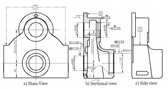
The process diagram details fixture clamping, references, constraints, surface and machining requirements, and clamping type.
For surfaces with specific requirements that are not machined, sectional views may be provided. The process diagram should be identical to the part drawing.

Two-surface-one-pin positioning is employed. To ensure complete positioning, six degrees of freedom must be constrained. The part processing sequence is shown in Figure 3.

Machining Schematic Diagram
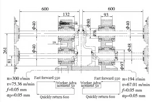
A machining schematic must show the positions of the spindle, clamping body, boring die, workpiece, and all feed and retract strokes.
This diagram reflects the part’s machining process and tool arrangement.
After setting the machine plan, the operator adds the cutting parameters to the schematic (Figure 4).

Fixture Design
Fixtures ensure machining accuracy by securing workpieces in precise positions prior to processing.
Engineers primarily categorize fixtures as specialized or universal. Turning, milling, drilling, and boring fixtures process various part types.
Specialized fixtures facilitate more efficient machining of similar parts compared to universal fixtures, enhancing productivity and reducing costs.
Components of Machine Tool Fixtures
Machine tool fixtures include: Locating Elements—components like plates, trimming, cylindrical, and diamond pins used to position the workpiece.
Clamping Elements: Components like chucks and plates used to secure the workpiece.
Tool-setting and guiding elements: Primarily guide the cutting position of the tool, such as boring bushings, orientation keys, and pointed keys;
Fixture Body: Connects all components to form an integrated assembly;
Other Devices or Components: Beyond the primary parts and mechanisms, some fixtures incorporate springs, boring jig supports, hinge mechanisms, bushings, etc.
Design Steps and Content
Positioning Analysis: Selects two-surface-one-hole positioning.
Automation is achieved using movable locating pins connected to servo-electric cylinders.
For the two surfaces:
– The first surface employs a locating plate to restrict 3 degrees of freedom.
– The second surface utilizes a sleeve outside the boring sleeve to tightly contact the workpiece, restricting 2 degrees of freedom.
– After restricting 5 degrees of freedom, complete positioning is still unattainable. Therefore, a chamfered pin is used as a locating pin inserted into a threaded hole to restrict one additional degree of freedom.
Direct insertion of the locating pin is difficult, so a 15° taper is added to its tip to ease entry when misaligned.
Driven by the servo electric cylinder, the chamfering pin extends as the locating pin and then retracts, achieving automatic positioning.
Guide Design: Single-sided rolling sleeves guide the boring bar for four holes, reducing runout and wear.
Limited hole spacing restricts bushing size, so guide bushings include “cutting guide grooves” when their inner diameter is smaller than the bore.
Orientation keys on rotating bushings, with long keyways milled in the sleeves and pointed keys near the front, ensure proper boring bar alignment.
Conclusion
Versatility and automation represent the primary design requirements for fixtures today and mark the developmental trajectory of fixture technology.
Modular fixtures provide high versatility, with preliminary design based on global research on modular machine tools and fixtures.
Draft the housing drawing and machining plan, then design modular fixtures with two-surface-one-hole positioning and CNC feed.
For the two surfaces:
– The first surface uses a locating plate to restrict 3 degrees of freedom.
– The second surface employs a sleeve fitted over the boring sleeve to tightly contact the workpiece, restricting 2 degrees of freedom.
After restricting 5 degrees of freedom, complete positioning remains unachievable. Therefore, a chamfered pin is used as a locating pin, inserted into a threaded hole to restrict one additional degree of freedom.
For locating and clamping, the fixture must be modularized. After disassembly, fixture components should be interchangeable with other fixtures.
Servo electric cylinders automate positioning and clamping, improving accuracy and efficiency.
Customize tool settings and clamping, using an externally rolled boring sleeve with guide grooves for modular automation.
