With technological advancements and market demands for cost reduction, the advantages of monolithic cast automotive chassis have become increasingly evident.
Conventional welded chassis are complex, deform easily, and weaken under heat; monolithic cast designs eliminate these problems. Monolithic chassis improve efficiency, strength, and precision, giving new energy vehicles a cost and performance advantage.
While monolithic chassis deliver clear functional advantages over traditional counterparts, they also introduce new challenges. Compared with conventional chassis, monocoque designs are larger and more complex, making casting and development more difficult.
While most automotive manufacturing and R&D companies recognize the benefits of monocoque chassis, they remain hesitant to adopt them. Key reasons include:
First, proven forming processes for monocoque chassis are lacking, as gravity casting large thin-walled parts is highly challenging.
Second, most automakers are still in early development, making prototype mold costs prohibitively high. Third, ensuring process feasibility and dimensional accuracy during the casting of large thin-walled components;
Fourth, the need for oversized sand molds to cast large components, including challenges in producing such molds while maintaining precision and contour accuracy.
This paper reports China’s first successful use of 3D printing to cast a large thin-walled aluminum alloy chassis, produced with the ASK Storm S1800 (3DP) sand mold printer.


Process Analysis and Design
The main challenges of 3D-printed sand molds in integrated chassis casting include:
- Complex geometry and large size (3806 × 1545 × 695 mm).
- Lightweight design uses 3–5 mm walls, reduced to 3 mm in subframes.
- Large thin-walled battery zones and subframes span a 670 mm height difference.
- The part requires CT10-level dimensional accuracy (GB/T 6414–2017).
- Casting requires tensile ≥270 MPa, elongation ≥5%, and yield ≥180 MPa.
Shrinkage ratios were set to 1:1.027 (Y), 1:1.021 (X), and 1:1.01 (Z) based on data and expertise.
Filling was challenging due to size and height; a top-pour 3D-printed sand mold optimized it.
Layered top–bottom pouring ensures complete, compliant casting.
Stepped symmetrical inlet fills subframes and battery pack (Fig. 3).
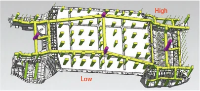
Fig. 4 shows 3 mm-thick areas far from gates, where ~30°C cooling causes cold shuts and gas entrapment.
Extra gates were added at problem points to fix side filling issues (red arrows, Fig. 4).
Two added gates prevent cold shuts and fill thin red-framed areas first.
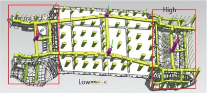
Thin-walled sides fill easily, but the large central surface remains challenging.
Sides fill, but the central surface resists flow, causing air entrapment and incomplete casting.
Casting tilted 3° along its width to aid gravity filling (Fig. 4).
The design ensures short flow paths, slow cooling, low resistance, and smooth filling.
3D-printed runners with variable flow rates ensured complete filling and solved long-path issues.
3D-printed sand molds with multi-directional channels ensure complete filling of thin battery surfaces.
Process redesigns quickly fix casting issues, reduce mold costs, and enable complex parts.
Fig. 5 shows multi-level pouring fills thin-walled sides with minimal temperature drop.
After side filling, the angled central surface fills under gravity.
Sides cool first (Fig. 5b) with shrinkage compensated; central surface, riser, and gates cool last.

Process feasibility confirmed; sand mold design and production followed.
Sand Mold Parting and Design
Traditional molds for such large, complex structural parts incur extremely high costs and require production cycles exceeding 90–120 days for delivery.
3D-printed sand molds significantly reduce costs and enable delivery within just 30 days.
Therefore, we extracted historical process data and mold assembly designs for chassis components from our proprietary process database.
The sand mold exceeded printer size, so precision assembly was used to meet design requirements.
Designing large, thin-walled molds with height differences is complex, requiring overall process planning before sectional mold assembly.
The integrated sand mold was based on the primary mold in Figure 6, designed as a four-layer, fifteen-piece, eight-ton assembly.
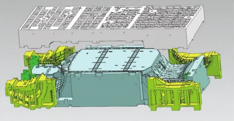
The sand mold’s lower, side, and upper sections use XYZ alignment and tongue-and-groove joints to ensure precise assembly (Figure 7).
Sand Mold Printing
The ASK Storm S1800 prints the full sand mold, forming a box of 1800 × 1000 × 730 mm.
Twelve sand boxes are planned, each printed in ~8 days, reducing cycle time and cost versus traditional methods.
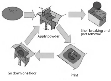
Sand mold design data is converted to SLT layers for printing. The 3DP inkjet process mixes furan resin and curing agent with sand, solidifying via cross-linking.
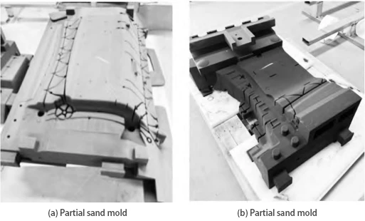
The equipment prints 0.35 mm sand layers with resin, solidifies them, and repeats until the mold is complete, then removes and cleans it (Figures 8–9).
Sand Mold Processing and Assembly
After printing, the sand mold is desanded and checked for dimensions, gas emission, and strength to reduce casting risks.
Required sand mold parameters:
Gas emission ≤ 12 mL/s
Tensile strength ≥ 1.2 MPa
Dimensional accuracy within ±0.1%
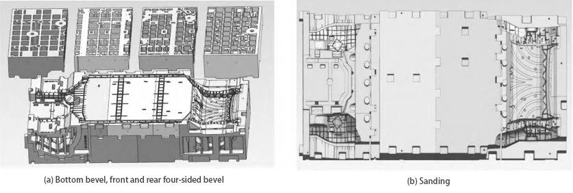
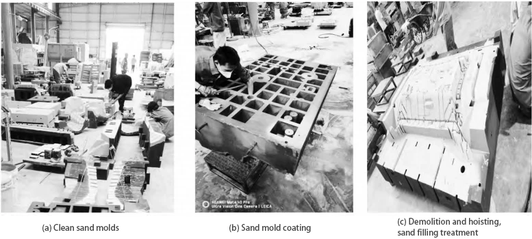
Upon passing all inspections, the sand molds proceed to surface treatment as shown in Figure 10.
Sand Mold Assembly
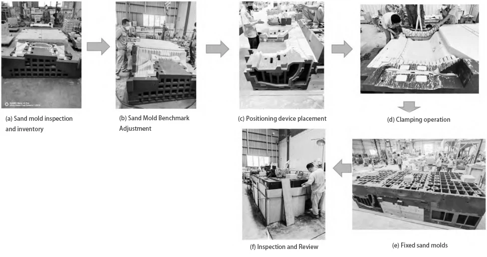
Following surface treatment, assemble the sand molds according to process guidelines as illustrated in Figure 11.
Melting and Casting
ZL101A (A356.2) was chosen for its required performance and fluidity. Melting follows strict steps: melting, slag removal, degassing, refining, and modification.
Due to its large size, the integrated chassis uses a gravity-fed multi-runner pouring design for precise control.
Unified on-site command and coordination enabled a single-operation pour at 760 °C ± 5 °C.
Casting cleanup and inspection
After the sand mold cools, castings are removed. Care must be taken during part extraction to prevent secondary deformation.
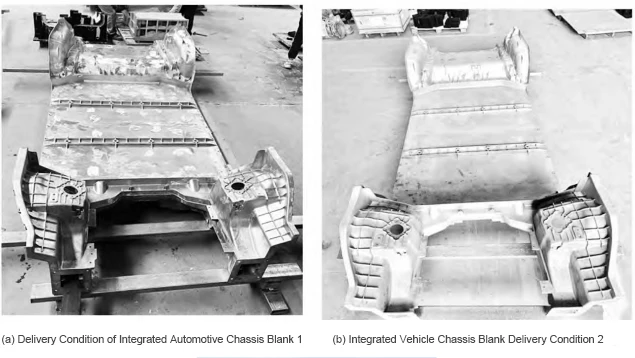
Post-extraction, a preliminary inspection confirms complete filling throughout the casting with no severe casting defects.
The casting (Figure 12) was checked with custom tools, confirming the process design’s validity.
- Part dimensional inspection:
– Length: Theoretical 3,806 mm, measured 3,803.7 mm, deviation <3 mm;
Theoretical width dimension: 1,545 mm; measured width: 1,543.1 mm, deviation < 2 mm;
Theoretical height 695 mm; measured 692.2 mm, deviation < 2.5 mm. Overall dimensions met CT10 tolerance requirements.
- Material properties of castings passed post-heat treatment testing.
To meet automotive chassis functional testing requirements, in-situ sampling tests yielded the following results:
Tensile strength ≥ 270 MPa
Yield strength ≥ 180 MPa
Elongation δ5 ≥ 5%
Hardness HB 80.
Project Summary: In 35 days, 3D printing and our database enabled rapid, pre-production validation of complex components for the new energy vehicle industry.
Conclusion
As 3D printing matures, its efficiency and cost will meet the needs of large-scale manufacturing. This paper shows 3D printing enables gravity casting of large thin-walled parts like integrated chassis and battery packs.
Tesla is exploring 3D-printed die-cast chassis with hollow features, advancing intelligent manufacturing.
Mature 3D printing enabled casting large thin-walled components, speeding automotive R&D, product development, and technological upgrades.
