
Computer Numerical Control (CNC) machine tools are widely used in modern manufacturing for their precision, efficiency, and automation capabilities.
Engineers can classify CNC machines in various ways depending on their functions, structures, and control methods.
This article introduces the main classification principles of CNC machine tools.
These include motion control trajectories, servo control systems, and functional levels.
It also covers different machining application categories, providing a systematic understanding of their types and characteristics.
There are many types and specifications of CNC machine tools, and the methods of classification vary.
Generally, we can classify them according to the following four principles based on their functions and structures:
Classification by the Control Trajectory of Machine Tool Motion
CNC Machine Tools with Position Control
In point-to-point control, we require only that the machine’s moving components accurately position from one point to another.
The requirements for the motion path between points are not strict.
No machining takes place during the movement, and the motions of the various coordinate axes are independent of one another.
To achieve both fast and precise positioning, the movement between two points generally begins with rapid movement, followed by a slow approach to the target point to ensure positioning accuracy.
The figure below illustrates the motion path for point-to-point control.
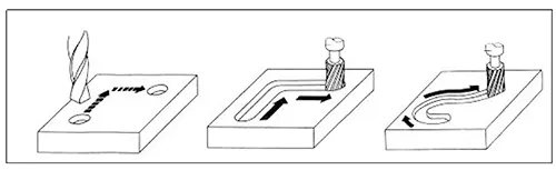
Machine tools equipped with point-to-point control primarily include CNC drilling machines, CNC milling machines, and CNC punch presses.
With the advancement of CNC technology and the decline in the cost of CNC systems, CNC systems used solely for point-to-point control have become rare.
Linear-Control CNC Machine Tools
Engineers define linear-control CNC machine tools (also known as parallel-control CNC machine tools) by their ability to control not only precise positioning between points but also the movement speed and path (trajectory) between two related points.
However, the movement path is limited to motion parallel to the machine tool’s coordinate axes.
In other words, we control only one coordinate axis at a time, meaning the CNC system does not need to perform interpolation calculations.
During the movement, the cutting tool can perform machining at a specified feed rate; generally, these machines can only process rectangular or stepped parts.
Machine tools with linear control capabilities primarily include relatively simple CNC lathes, CNC milling machines, and CNC grinding machines.
Engineers also refer to the CNC systems for these machines as linear control CNC systems. Similarly, CNC machine tools used exclusively for linear control are relatively rare.
Contour-Control CNC Machine Tools
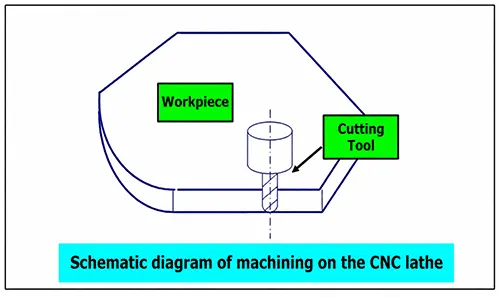
Contour-controlled CNC machine tools, also known as continuously controlled CNC machine tools, are characterized by their ability to simultaneously control the displacement and speed of two or more motion axes.
To ensure that the relative motion trajectory of the cutting tool along the workpiece contour meets the workpiece’s machining requirements, we must precisely coordinate the displacement and speed of each axis according to specified proportional relationships.
Therefore, this type of control requires the CNC unit to have interpolation capabilities.
Interpolation refers to the process of describing the shape of a straight line or an arc based on the basic data input in the program, such as the end-point coordinates of a straight line, the end-point coordinates of an arc, and the center coordinates or radius of a circle.
It is carried out through mathematical processing by the interpolation unit within the CNC system to generate the shape of a straight line or arc.
In other words, while performing calculations, the system distributes pulses to the controllers of each coordinate axis based on the calculation results, thereby ensuring that the coordinated displacement of the axes matches the required contour.
During the motion, the cutting tool continuously cuts the workpiece surface, enabling the machining of various straight lines, arcs, and curves.
The machining path of contour control.
Major types of such machine tools include CNC lathes, CNC milling machines, CNC wire-cut EDM machines, and machining centers.
Engineers refer to the corresponding CNC units as contour-controlled CNC systems.
Depending on the number of coordinated axes they control, they can further classify these systems into the following types:
① Two-axis interpolation: Primarily used for machining rotational surfaces on CNC lathes or curved cylindrical surfaces on CNC milling machines.
② Two-and-a-half-axis interpolation: Primarily used for controlling machine tools with three or more axes, where two axes can move in interpolation while the third axis performs periodic feed.
③ Three-axis interpolation: This is generally divided into two categories. One category involves the interpolation of the three linear coordinate axes (X, Y, and Z), which is commonly used in CNC milling machines and machining centers.
The other category involves simultaneously controlling two of the three linear coordinate axes (X, Y, and Z) while also controlling a rotational axis that rotates around one of those linear axes.
For example, in a turning machining center, we control not only the interpolation of the longitudinal (Z-axis) and transverse (X-axis) linear axes but also the spindle (C-axis), which rotates around the Z-axis, simultaneously.
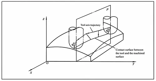
④ Four-axis interpolation: Simultaneous control of the three linear axes (X, Y, Z) in conjunction with a single rotational axis.
⑤ Five-axis interpolation: In addition to simultaneously controlling the three linear axes (X, Y, Z), this also involves simultaneously controlling two of the A, B, or C axes—which rotate around these linear axes—resulting in the simultaneous control of five axes.
This allows us to position the cutting tool in any orientation in space.
For example, by controlling the tool to swing simultaneously around both the X-axis and Y-axis, we ensure that the tool always maintains a direction perpendicular to the contour surface being machined at the cutting point.
This ensures the smoothness of the machined surface, improves machining accuracy and efficiency, and reduces the surface roughness of the workpiece.
Classification by Servo Control Method
Open-Loop Control CNC Machine Tools
The feed servo drive in this type of machine tool is open-loop, meaning it lacks a feedback detection device.
Typically, the drive motor is a stepper motor. The main characteristic of a stepper motor is that the motor rotates by one step angle each time the control circuit changes the command pulse signal, and the motor itself has self-locking capability.
The feed command signals output by the CNC system control the drive circuit via a pulse distributor.
They control coordinate displacement by varying the number of pulses. They control displacement speed by varying the pulse frequency.
They control displacement direction by varying the pulse distribution sequence.
Therefore, the most notable features of this control method are its ease of control, simple structure, and low cost.
Since the command signal stream emitted by the CNC system is unidirectional, there are no stability issues with the control system.
However, because errors in mechanical transmission are not corrected via feedback, displacement accuracy is not high.
Early CNC machine tools all employed this control method, though they had a relatively high failure rate.
Currently, thanks to improvements in drive circuits, it remains widely used.
In China, in particular, we commonly adopt this control method in general-purpose, economical CNC systems and in the retrofitting of older equipment with CNC capabilities.
Additionally, this control method allows for the use of a microcontroller or single-board computer as the CNC unit, thereby reducing the overall cost of the system.
Closed-Loop Control Machine Tools
The feed servo drives in this type of CNC machine tool operate using a closed-loop feedback control method.
Engineers can use either DC or AC servo motors as drive motors.
The system must include position and speed feedback to continuously monitor the actual displacement of moving components during machining.
They then feed this data back to the comparator in the CNC system, which compares it with the command signal generated by the interpolation calculation.
The resulting difference serves as the control signal for the servo drive, thereby driving the moving components to correct any displacement errors.
We further classify this system into two control modes—fully closed-loop and semi-closed-loop—depending on the installation location of the position feedback sensors and the type of feedback device used.
1. Fully Closed-Loop Control
As shown in the figure, the position feedback device uses a linear displacement sensor (currently, a linear encoder is generally used), which is mounted on the machine tool’s saddle.
This directly detects the linear displacement of the machine tool’s coordinates.
Through feedback, we can eliminate transmission errors throughout the entire mechanical transmission chain—from the motor to the machine tool saddle—thereby achieving very high static positioning accuracy for the machine tool.
However, since the friction characteristics, stiffness, and backlash of many mechanical transmission components within the control loop are nonlinear, this poses considerable challenges for stability correction in the closed-loop system.
This is further compounded by the fact that the dynamic response time of the entire mechanical transmission chain is significantly longer than the electrical response time.
System design and tuning are also quite complex.
Therefore, this fully closed-loop control method is primarily used in CNC coordinate grinding machines and CNC precision grinding machines that require very high precision.
2. Semi-Closed-Loop Control
As shown in the figure, position feedback is provided by an angle detection device (currently mainly encoders), which is directly mounted on the end of the servo motor or lead screw.
Since we do not include most mechanical transmission components in the system’s closed-loop circuit, we can achieve relatively stable control characteristics.
Mechanical transmission errors, such as those in the lead screw, cannot be corrected in real time through feedback.
However, we can appropriately improve their accuracy using software-based fixed-value compensation methods.
Currently, most CNC machine tools employ a semi-closed-loop control method.
Hybrid Control of CNC Machine Tools
Engineers can develop a hybrid control scheme by selectively combining the characteristics of the control methods described above.
As mentioned earlier, open-loop control offers good stability and low cost but has poor accuracy, while fully closed-loop control has poor stability.
Therefore, to compensate for these shortcomings and meet the control requirements of certain machine tools, it is advisable to adopt a hybrid control approach.
The two most commonly used methods are open-loop compensation and semi-closed-loop compensation.
Classification by Functional Level of CNC Systems
Based on their functional level, CNC systems are typically classified into three categories: low, medium, and high.
This classification method is widely used in China.
The boundaries between these three categories are relative, and the criteria for classification may vary across different periods.
Given the current state of development, we can classify various types of CNC systems into low, medium, and high categories based on certain functions and performance indicators.
Among these, medium- and high-end systems are generally referred to as full-featured CNC or standard-type CNC.
Metal-Cutting Category
This refers to CNC machine tools that employ various cutting processes such as turning, milling, planing, reaming, drilling, grinding, and planing.
Engineers can further divide it into the following two categories.
① General-purpose CNC machine tools: such as CNC lathes, CNC milling machines, and CNC grinders.
② Machining Centers: Their main feature is a tool magazine with an automatic tool-changing mechanism.
After we clamp the workpiece once, we automatically change various tools to continuously perform multiple machining operations on all machined surfaces of the workpiece on the same machine.
These operations include milling (turning), reaming, drilling, and tapping.
Examples include (turning/milling) machining centers, turning centers, and drilling centers.
Metal Forming
This category refers to CNC machine tools that use forming processes such as extrusion, punching, pressing, and drawing. Common examples include CNC presses, CNC press brakes, CNC pipe benders, and CNC spin formers.
Special Machining
This category primarily includes CNC wire EDM machines, CNC die-sinking EDM machines, CNC flame cutting machines, and CNC laser processing machines.
Measurement and Plotting Category
This category primarily includes coordinate measuring machines (CMMs), CNC tool setters, and CNC plotters.
Conclusion
In summary, we can categorize CNC machine tools from multiple perspectives, each reflecting different aspects of their structure and operation.
Whether classified by motion control (point-to-point, linear, and contour control), servo systems (open-loop, closed-loop, and hybrid control), or application functions (metal cutting, forming, special machining, and measurement), these classifications help clarify the diversity and specialization of CNC technology.
Understanding these categories is essential for selecting the appropriate machine tools and optimizing manufacturing processes in modern industrial production.