
With the rapid development of aircraft engines, efficient and reliable sealing devices are required between components to prevent gas or liquid leaks and ensure the engine’s stability and operational efficiency.
In particular, the bearing chamber contains lubricating oil, which must be prevented from leaking into other components; at the same time, external gases must be prevented from entering the bearing chamber to maintain normal system operation. grease sealing assemblies are typically used for this purpose.
A typical grease sealing assembly includes a seal housing, grease ring, wave spring, retaining ring, a mounting ring, a support ring, and a sealing ring.
The machining quality of the seal housing components directly determines the sealing performance of the seal assembly.
Existing Machining and Sealing Challenges
Graphite components are prone to damage during assembly, and the pass rate for airtightness testing is low; with the current first-pass yield rate standing at 30%.
The sealing components are manufactured by Dongtan and come with certificates of conformity; their performance has been professionally tested and found to be satisfactory.
Analysis indicates that the individual components are deformed, particularly regarding its M-face, which requires a flatness of 0.0012 mm, a surface roughness of Ra 0.1, and perpendicularity to reference A of Ø 0.01 mm.
It is difficult to consistently ensure these key parameters, resulting in gaps between the sealing components during assembly, gaps exist between the various sealing components, leading to sealing failure. This, in turn, affects the delivery schedule of the parts.
If the sealing performance of the parts is poor, it significantly impacts the operational performance of the turbine bearing components, which in turn affects the engine’s operational performance.
Research Objectives
In view of this, this paper focuses on seal seat components.
By analyzing the structural characteristics and machining challenges of these components, a reasonable manufacturing process is established to produce parts that meet the requirements of the design drawings. The main research content of this paper is as follows:
(1) Increasing the part acceptance rate to over 80%;
(2) Optimizing the machining process route and controlling deformation;
(3) Optimizing milling parameters to improve machining efficiency;
(4) Development of specialized tooling and measuring fixtures;
(5) Exploration of assembly methods;
(6) Refinement of sealing test methods.
Machining Challenges for Seal Seat Parts
The 2D sketch of the seal seat part is shown in Figure 1. Based on our analysis, the main machining challenges for this part are as follows.
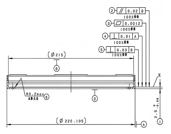
(1) The part has thin walls and requires the machining of multiple grooves and small holes, resulting in deformation after machining;
(2) The high-precision outer diameter is Ø220.10(0/-0.025) mm; with a minimum wall thickness of 2.5 mm, this dimension is highly prone to becoming elliptical after machining;
(3) After deformation of Reference A, the perpendicularity of the inner end face to Reference A (tolerance Ø0.01 mm) is difficult to ensure;
(4) The parallelism of the inner end face to Reference D (tolerance 0.02 mm) is prone to local out-of-tolerance conditions;
(5) The flatness of the inner end face is 0.012 mm, with a surface roughness of Ra 0.1, making grinding difficult;
(6) During assembly, the graphite seal is prone to damage, and improper operating procedures may occur; furthermore, the assembly documentation for the graphite seal assembly is not available on-site.
Analysis of Part Machining Solutions
Analysis of issues with the machined part reveals that the primary factors affecting the product are an unreasonable original process route and problems with part clamping and positioning.
The bottom surface of the part was cut using slow-wire EDM, and the six grooves (560 mm) machined via wire cutting did not meet the +0.2 tolerance requirement.
Furthermore, the part exhibited some deformation after groove machining.
The original process route did not include a step for re-establishing the reference surface, and it is very difficult to grind the sealing end face directly from the lathe’s Ra 1.6 finish to Ra 0.1.
Corresponding measures will be taken to refine and compile the existing process specifications.
Process Optimization Measures
The specific plan is as follows:
(1) Analyze the part’s machining process route, identify existing issues, and compile formal process specifications;
(2) Except for groove E, which is permitted to be machined using electrical discharge machining (EDM), all other grooves and holes will be machined using CNC milling;
(3) To control part deformation, first perform vacuum stress-relief heat treatment after rough turning, followed by finish turning;
Next, machine the holes and slots;
Then use wire EDM to cut off the machining bosses; finally, perform precision grinding to eliminate stress-induced deformation from the semi-finish machining process, thereby ensuring part quality;
(4) For the machining of the part’s sealing end face, precision turning is performed first, followed by sequential clamping and grinding of the inner bore and end face to ensure a surface roughness of Ra 0.8 for the sealing end face and a parallelism of 0.015 mm relative to reference D;
Second, grind the outer circumference using the precision-machined inner bore and end face as support and positioning references;
Finally, lapping is performed on the sealing end face to ensure a surface roughness of Ra 0.1 and compliance with technical specifications;
Process Verification and Documentation Improvement
(5) Use Vericut software to perform simulation analysis of the milling process to verify the correctness of the program, and use the Force module to optimize the part’s feed rate (F) to improve machining efficiency;
(6) Revise Process Specification 881 to systematically incorporate the cleaning and assembly requirements for the graphite seal assembly specified in the design documents into the process specification, facilitating on-site operations;
(7) Compile statistics on issues encountered during trial machining and revise the process specification accordingly.
Process Sequence Planning and Implementation Results for Part Machining
To address the machining challenges of this part, we focused on several key areas:
First, resolving issues related to part deformation, difficulties in grinding high-precision sealing surfaces, challenges in meeting technical specifications, and a lack of detailed assembly requirements.
Engineers formulated a preliminary implementation plan and conducted trial machining on several parts according to the newly developed formal process specifications.
They further validated the plan while revising the assembly process specifications.
(1) Engineers developed the process specifications based on the implementation plan.
These specifications included the design of process bosses to facilitate rough and semi-finish machining of the parts, thereby improving machining efficiency.
(2) Since this is a trial machining process, the finishing stage employs a combination of custom-made fixtures and modular fixtures to address the lack of dedicated fixtures for the parts.
The fixture design utilizes an “axial clamping” method, and the clamping method must ensure that the clamping points coincide with the support points to prevent clamping deformation of the parts.
(3) Engineers used Vericut software to simulate and optimize the milling program.
(4) Engineers revised the assembly process specifications and refined the testing methods.
Optimized Machining Process
After analyzing the part’s machining plan, engineers rewrote the formal process specifications to implement the proposed plan.
The specific process sequence is as follows: Forging → Turn end faces and outer diameter → Turn end faces, outer diameter, and bore → Turn end faces, outer diameter, and bore → Wire EDM → Deburring → Cleaning → Intermediate inspection → Cleaning, oil seal → vacuum heat treatment → grinding of reference surfaces → deburring → turning of internal and external contour surfaces → deburring → drilling and milling of grooves → deburring → EDM grooving → wire cutting to sever → grinding of flat surfaces → grinding of internal bores and end faces → Grinding outer diameter → Deburring, polishing → Lapping bottom end face → Cleaning → Magnetic particle inspection → Cleaning → Marking → Final inspection → Washing, oil sealing → Chemical passivation → Pre-storage inspection → Oil sealing, packaging.
Tooling and Trial Production
Since the project is in the pilot production stage, engineers use in-house-made fixtures combined with modular fixtures to solve the problem of insufficient part fixturing.
Therefore, they do not request any special-purpose fixtures.
The existing special T-slot cutter No.
Engineers have incorporated 13B153-037 and measuring tool B2φ60731-062 into the process specifications to facilitate part machining.
During trial production and part machining, engineers continuously identified and resolved issues. Table 1 presents the specific details.
| No. | Part Name | Change Order No. | Main Changes |
|---|---|---|---|
| 1 | Seal Seat | YG-1758 | Process 110: Correct the value of flatness ③, changing it from 0.012 mm to 0.0012 mm. |
| 2 | Seal Seat | YG-0256 | Process 60: Change dimension ⑦ and increase the machining allowance. |
| 3 | Seal Seat | YG-1796 | Add a sign-off/checkpoint for the chemical passivation process and clarify the inspection method for dimensions ① and ② in Process 105. |
| 4 | Seal Seat | YG-1946 | Process 70: Change dimension ② to R-gauge inspection; change dimension ⑪ to B2 φ60731-062 inspection; add a dedicated T-shaped cutter No. 13B153-037. Process 135: Change dimensions ㉒ and ㉘ to B2 φ60731-062 inspection; change dimension ㉗ to R-gauge inspection. |
| 5 | Seal Seat | YG-1959 | Process 70: Clarify the inspection method for dimension ⑪. |
| 6 | Seal Seat | YG-2084 | Process 110: Change dimensions ④ and ⑤ to measurement inspection; inspect the chamfered edges by visual inspection. |
| 7 | Seal Seat | YG-2426 | Complete the process flow chart according to the standardized requirements. |
| 8 | Seal Seat | YG-2307 | Processes 10, 15, 20, and 30: Clarify that the dimension 1.5 ± 0.5 mm applies to 6 locations. |
| 9 | Seal Seat | YG-0221 | Implement the design change order throughout the process. Incorporate the requirements for cleaning, assembly, testing, and packaging of graphite parts into the process specifications to facilitate on-site production. |
| 10 | Seal Seat | YG-1837 | Conduct a review of Processes 15 and 30 and clarify the bending condition of the part. |
The new process route enabled engineers to manufacture all parts that passed inspection.
The inspection results showed no deformation, and the parts fully met the requirements specified in the design drawings.
3D Simulation Analysis
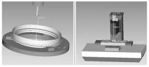
Using Vericut software can effectively identify minor issues in milling programs, making the part machining process more intuitive.
By reviewing the program, users can view the machining status of each program block in real time. Using the Force module to optimize the part’s program makes the machining process smoother and improves machining efficiency.
See Figure 2 for the Vericut 3D simulation of the part.
Using Vericut software for CNC milling simulation and collision detection allows for verification of program correctness, preventing machine collisions caused by programming errors and avoiding major safety incidents.
At the same time, checking for syntax errors in the program greatly improves the efficiency of manual program verification, enhances the efficiency of program modifications following UG post-processing, and verifies the correctness of the program.
There are two optimization methods for setting optimal parameters for each cutting tool:
(1) Optimization Using the Constant Volumetric Removal Rate Cutting Method.
When the tool removes a large volume of material per unit time, engineers reduce the feed rate; when the removed material volume decreases, they increase the feed rate.
Engineers primarily apply this optimization method to machining operations with significant variations in material allowance.
(2) Constant Cutting Thickness Optimization.
This optimization method maintains a constant cutting thickness during machining by varying the feed rate.
This optimization mode mainly supports semi-finishing and finishing operations, and it improves machining efficiency and part surface quality.
Key Technical Innovations
Innovative Process Route Design
As this is a typical rotary part, turning is the primary machining method used for both roughing and semi-finishing.
During rough machining, engineers use a shared machining boss to conserve raw material.
They then cut off the part and perform vacuum stress-relief heat treatment to adjust the stress distribution.
Engineers grind the bottom end face of the part to establish the reference surface for clamping.
They then carry out semi-finishing turning and milling operations.
After removing the process shoulder, engineers move the part into the finishing stage.
Engineers complete this stage entirely through grinding operations, including flat grinding of the end face, internal bores, and external cylindrical surfaces.
This approach eliminates the influence of machining deformation caused during the semi-finishing process on high-precision dimensions.
Finally, engineers precision-lap the inner end face of the part to ensure machining quality.
Visual Adjustment of Cutting Parameters
Vericut optimization involves simulating the cutting process to generate a cutting model.
Based on the tool currently in use and the toolpath for each step, it calculates the cutting volume for each program step and compares it with empirical cutting parameters or the cutting parameters recommended by the tool manufacturer.
After analysis, when the remaining material is large, Vericut reduces the speed; and when the stock allowance is small, it increases the speed, thereby modifying the program to incorporate new feed rates.
Engineers use Vericut software to simulate the machining process and set the cutting thickness to 0.025 mm.
They ensure that the simulated tool information and part material match the actual machining conditions, enabling batch visualization and adjustment of CNC programs.
The optimized program results in a smoother machining process, reduces tool tip wear, and improves part machining efficiency.
Figure 3 shows the CNC programs before and after optimization.

(3) Implementing Process Management Using the PDCA Cycle
During the machining analysis of this part, engineers developed manufacturing procedures, communicated with the design team, requested tooling, scheduled part production, and tracked the machining process.
These tasks ensured a comprehensive evaluation of the part’s machining requirements.
We also conducted a comprehensive analysis of the results of each process, retained the successful outcomes, and addressed the areas needing improvement by initiating the next round of the PDCA cycle.
Conclusion
By rationally designing the machining process sequence and incorporating machining features into the part design, we have not only resolved the part clamping issues but also improved machining efficiency.
The machining process includes rough machining, semi-finish machining, and finish machining, while engineers integrate vacuum stress-relief heat treatment and precision grinding for correction to control part deformation.
By employing precision turning, precision grinding, and finally precision lapping, we have resolved the challenge of achieving the required flatness of 0.0012 mm and surface roughness of Ra 0.1 on the sealing end face.