
The tank bottom flange is a critical component of the pressurized delivery system in liquid-fueled launch vehicles, consisting of a main structure and a sealing structure.
During manufacturing and machining, due to constraints such as the position, size, and precision requirements of the sealing structure, a process involving separate machining followed by welding is often employed.
However, this approach presents the following issues:
1) Deformation of the flange surface caused by welding affects the sealing dimensions and subsequent welding of the flange to the tank;
2) The large number of welds means that even a single welding defect can compromise strength and reliability;
3) The process involves welding, defect detection, and repair welding, making the workflow cumbersome and complex.
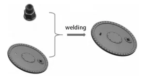
CNC milling is a machining process for forming integral flanges on solid eccentric nozzles;
it is an environmentally friendly and viable solution that can ensure compliance with theoretical dimensions.
However, due to constraints such as the position of the eccentric nozzle and stringent dimensional accuracy requirements, a mature and reliable process solution has long been lacking.
Problem Analysis
Product Scope
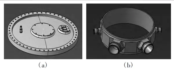
Figure 2 shows a common type of integrated flange used in a certain model of liquid-fueled rocket.
These flanges consist of a main structure and several sealing structures, which are positioned at various locations and are offset from the main structure’s axis of rotation, forming a specific angle with it.
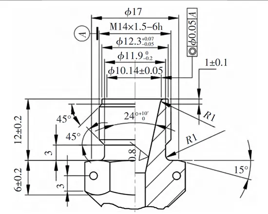
Flange diameters range from 100 to 1,000 mm. A magnified view of a specific type of sealing structure is shown in Figure 3.
Its inner opening features a tapered design with a cone angle of 24° to 24°10′ and a tapered opening diameter of (10.14 ± 0.05) mm, with a concentricity requirement of 0.05 mm relative to the outer side.
Whether in a split or monolithic design, the relevant requirements of the sealing structure determine the key parameters for the housing’s airtightness and pressurized conveyance.
The material for monolithic flanges is typically 2219 aluminum alloy forgings;
since the forging dimensions encompass both the main structure and the sealing structure, this often results in a material removal rate of 85% or higher.
Analysis of Challenges
Based on the product analysis above, the core challenge in manufacturing integrated flanges lies in ensuring the dimensional accuracy of the sealing surfaces, which presents the following difficulties.
1) Machining Deformation.
The nozzle structure is often smaller in dimension than the main flange structure.
Additionally, the nozzle is eccentrically positioned and surrounded by thin-walled structures, so flutter deformation during machining directly affects the finished product’s dimensions.
Furthermore, a significant amount of material is removed from the forging; as residual stresses are released following material removal, substantial machining deformation can occur.
The release and control of such deformation are critical.
2) Sealing precision.
For split-structure flanges, the sealing dimensions of the pipe nozzle are ensured through turning. However, due to the high precision requirements and the fact that some dimensions cannot be measured directly, a combination of templates and iterative measurements is often used to verify that the sealing dimensions are correct.
In contrast, the pipe nozzle position in integral flanges is often eccentric, making traditional turning processes inapplicable.
Therefore, determining how to use integral milling to ensure the sealing dimensions of the pipe nozzle is a critical issue that urgently needs to be resolved.
Technical Solution
In response to product manufacturing requirements and technical challenges, this paper presents a full-process integrated milling process for flanges with eccentric nozzles.
It provides an overall plan for the entire turning and milling process of integrated flanges, including roughing and finishing operations, as well as methods for deformation control.
Additionally, to meet the high-precision requirements of the sealing structure, this paper proposes a milling method for the tapered bore of the eccentric nozzle, as well as a compensation method for precision correction based on template inspection.
These approaches are specifically designed to ensure the precision requirements for the transition from turning to milling in the sealing structure.
Integrated Milling Process Plan for Monolithic Flanges
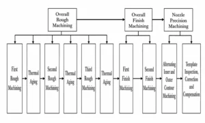
The overall process plan for the integrated milling of monolithic flanges is shown in Figure 4. It is divided into three parts: monolithic rough machining, monolithic finish machining, and precision machining of the pipe nozzle.
For the machining of internal and external contours, rough machining is performed using a method that alternates between three-axis milling and aging to progressively relieve deformation.
For the eccentric nozzle, all feature machining is completed within a single post-finishing operation, ensuring high positional accuracy requirements.
This process includes reference surface machining, allowance coordination, thermal and aging stress relief, and determination of milling allowances.
1) Turning Reference Surfaces.
During the rough machining of the blank, reference surfaces are machined first to facilitate subsequent allowance coordination during milling.
Turning reference surfaces involve machining the outer diameter and end faces to transform the blank into a standard cylinder.
2) Random multi-point contour measurement program.
During the milling process, the roughing stage requires allowances to account for deformation, while the finishing stage must ensure product accuracy;
Therefore, the process must perform measurements concurrently with machining throughout the entire operation.
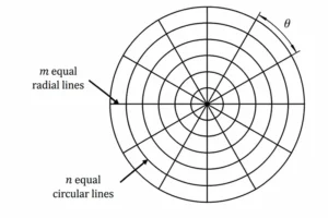
As shown in Figure 5, the process maintains the wall thickness of the central spherical surface throughout machining.
The method divides the generatrix of the spherical surface into m equal segments and divides the circumference into n equal segments.
It randomly selects more than two-thirds of the divided regions for program-controlled point sampling and thickness measurement, with the specific values of m and n listed in Table 1.
| Parameter | First Rough Machining | Second Rough Machining | Third Rough Machining | First Finish Machining |
|---|---|---|---|---|
| m | 6 | 12 | 18 | 24 |
| n | 3 | 3 | 6 | 6 |
Table 1. Specific Values for m Generatrix Divisions and n Circumferential Divisions
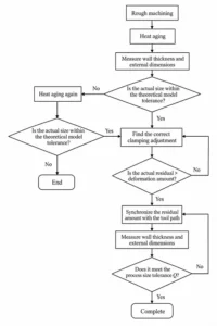
3) Turning-Assisted Allowance Adjustment.
Because deformation occurs after both the first and second rough milling operations, the process uses turning as an auxiliary method to adjust the allowances.
During the turning of the inner and outer contours and end faces, including the theoretical machining areas for subsequent operations, the process sets the dimensional tolerance after each rough machining operation to Q.
Figure 6 shows the turning-assisted allowance adjustment process.
4) Milling Allowance Control Method.
The integrated flange with an eccentric nozzle contains multiple features, and the rough machining process removes a large amount of material.
Setting the allowance for each step too small makes it difficult to control machining-induced deformation.
Setting the allowance too large reduces machining efficiency and may prevent the process from achieving the required surface quality and accuracy of the integrated flange.
Therefore, the proper setting of milling allowances is crucial, as they directly affect the final precision of the product.
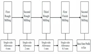
Following the principle of layer-by-layer machining to reduce the remaining material, the allowances after the first, second, and third rough milling operations are 4, 2, and 1 mm, respectively.
The allowance after the first finish milling is 0.5 mm, and the second finish milling brings the basic shape to the required dimensions.
Milling of Eccentric Nozzles and Methods for Accuracy Correction
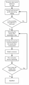
The tapered bore milling process of an eccentric nozzle represents a critical step in the finishing operation, and Figure 8 illustrates the specific process flow.
Traditionally, manufacturers used turning methods to machine nozzles.
However, compared to turning a standalone nozzle component, milling an eccentric nozzle within an integrated flange is more prone to chatter.
To minimize deformation of the eccentric nozzle during the milling process, the study first proposes an alternating milling strategy for the inner and outer contours of the eccentric nozzle.
It then applies a precision correction calculation method based on template inspection, refines the theoretical model, and generates the corresponding machining program.
1) Alternate milling of the inner and outer contours of the eccentric nozzle.
The setting of the machining allowance for the eccentric nozzle affects the final dimensional accuracy of the product.
The final theoretical model and the characteristics of radial deformation determine the milling strategy for the inner and outer contours.
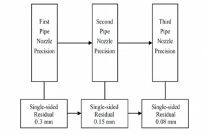
The process divides the alternate milling operation into three passes (as shown in Figure 9) and leaves allowances of 0.30, 0.15, and 0.08 mm, respectively.
2) Calculation method for accuracy correction based on template inspection.
Inspection method: The operator performs real-time inspection using a standard nozzle template.
The inspection process qualifies the product as conforming when the small end of the template passes through the nozzle’s tapered bore and fits tightly against the nozzle’s upper surface without any gap.
Meanwhile, the large end of the template cannot fully pass through the tapered bore and maintains a gap from the nozzle’s upper surface.
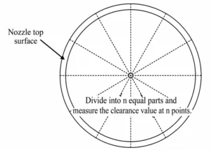
Measurement of Clearance Value and Average Calculation
Let δ be the clearance value at the through-hole of the prototype. Measure the clearance using a standard feeler gauge.
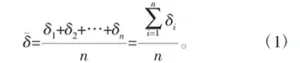
To eliminate measurement errors, take measurements at multiple locations and calculate the average value δ, with no fewer than three measurements taken at each location using the feeler gauge (see Figure 10).
The formula for calculating the average value δ is formula 1.
Definition of Key Geometric Parameters
The study defines the tip of the fillet extending from the eccentric nozzle as the inner diameter of the tapered bore on the upper surface of the nozzle, which measures (10.14 ± 0.05) mm (as shown in Figure 3).
The following sections designate this dimension as dz ± 0.05.
Let α be the angle of the tapered bore in the eccentric nozzle (which is the same as the angle of the template), and S be the allowance (i.e., the allowance for the eccentric nozzle corresponding to the clearance value δ).
Relationship Between Tapered Bore Machining Parameters
Machining the tapered bore on the inner surface of the nozzle is a critical process for ensuring the accuracy of the eccentric nozzle.
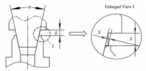
The angle α of the tapered bore in an eccentric nozzle, the allowance S, and the clearance δ are related by the following functional relationship:

3) Model correction based on the template inspection calculation method.
The accuracy correction calculation method based on template inspection determines the allowance S for an eccentric nozzle.
It uses the actual allowance to correct the theoretical model of the previous process.
This method converts the calculated correction values into adjustments to the theoretical model, enabling the gradual production of qualified products that meet the drawing requirements.
Test Results
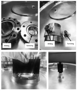
The study selected two typical sealing structures—conical and trapezoidal sealing lips—and manufactured the flanges using traditional split-piece turning and integrated milling methods, respectively.
The products machined using the split-piece turning method were smaller in size; this traditional turning process did not include aging treatment during machining. The integrated milling process employed the method proposed in this paper.
Upon completion of machining, all performance indicators of the sealing structures met the specified standards, and both passed the airtightness test on the housing.
Additionally, to further analyze the precision control of the sealing structures, this study conducted quantitative CMM inspections on both types of flange sealing structures.
Each inspection measured at least 8 points, with surface roughness determined by comparison with a reference sample.
Table 2 presents the results.
| Typical Sealing Type | Parameter | Specification | Split Machining | Integral Milling |
|---|---|---|---|---|
| Conical Seal | Taper Hole Inner Diameter (mm) | 10.14 ± 0.05 | 10.13–10.18 | 10.11–10.17 |
| Taper Angle | 24°–24°10′ | 24.052° | 24.099° | |
| Concentricity (mm) | 0.050 | 0.030 | 0.035 | |
| Surface Roughness (μm) | Ra0.8 | Qualified | Qualified | |
| Tapered Seal | Dimension 1 (mm) | 69 ± 0.03 | 68.97–69.02 | 68.98–69.02 |
| Dimension 2 (mm) | 4.13–4.17 | 4.14–4.16 | 4.13–4.16 | |
| Angle (°) | 60 ± 0.50 | 60.10 | 60.15 | |
| Surface Roughness (μm) | Ra0.8 | Qualified | Qualified |
Table 2. Test Results of Several Sealing Structure Types
Conclusion
This paper addresses the requirements for the integrated manufacturing of tank bottom flanges.
It proposes a comprehensive milling process for integrated flanges with eccentric nozzles, develops a milling method for the tapered bore of the eccentric nozzle, and introduces an accuracy correction and compensation method based on template inspection.
This method effectively controls machining deformation and ensures the precision of the sealing structure. As verified by comparative tests, the milling method for integrated flanges with eccentric nozzles can meet the manufacturing requirements for liquid rocket tank bottom flanges.
Future research will focus on the efficient manufacturing of integrated flanges.