
With the continuous advancement of technology, 5-axis CNC machine tools have seen significant improvements in various aspects, including workpiece clamping, the spindle and its supporting systems, and the servo systems.
These technological advancements have significantly improved part precision and machining efficiency while effectively reducing labor and machining costs.
When machining products with complex curved surfaces, end mills and ball-nose cutters are the most commonly used tools;
however, both have obvious shortcomings. By comparing ring cutters, flat-bottom cutters, and ball-nose cutters, this article highlights the advantages of ring cutters.
Advantages of Ring End Mills
Compared to Ball-Nose End Mills
When machining a workpiece with a ball-nose end mill, its spherical bottom surface allows for self-adjustment (meaning the curvature of the tool’s normal line always remains equal to the tool’s radius).
This makes it much easier to calculate the distance between the ball-nose end mill and any potential interference.
However, this also presents some issues. For example, the chip-trapping area at the top of a ball-nose end mill is relatively small, which creates certain difficulties for chip evacuation.
Furthermore, the cutting edges of a ball-nose end mill have varying cutting rates at different positions; particularly near the tip of the tool, the cutting rate is zero, thereby reducing the cutting efficiency of the bottom surface.
Furthermore, if no pressure is applied to the center of the tool, the likelihood of tool chatter during machining is significantly reduced.
These shortcomings prevent improvements in the production efficiency and surface finish quality of ball-end mills. However, compared to ball-end mills, ring-end mills demonstrate significantly superior surface finish quality during the manufacturing process.
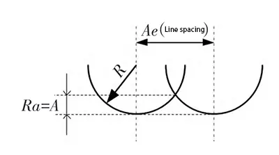
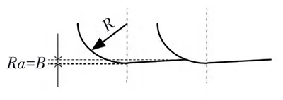
Furthermore, the cutting speed of ring end mills is significantly higher than that of ball-nose end mills.
While maintaining the same surface quality, the feed rate of a ring end mill is several times that of a ball-nose end mill;
consequently, the total cutting length is reduced, which significantly shortens the machining time, as shown in Figures 1 and 2.
Assuming only the tool’s arc-shaped cutting edge is used, and provided that part machining is not compromised, a ring cutter can be selected with a larger diameter, which will correspondingly increase the tool’s rigidity.
Comparison with Flat-Bottom Milling Cutters
Due to their structural characteristics, flat-bottom milling cutters can achieve a relatively large cutting width during machining.
However, because the cutting edge of a flat-bottom milling cutter consists of the intersection of its flank and top, this structure leads to two problems:
First, this cutting action accelerates tool wear;
Second, the actual cutting of the workpiece surface is primarily performed at the intersection of the peripheral edge and the top at the cutting tip, which results in poor surface finish on the final product and increases the challenges of subsequent production steps.
When using flat-bottom end mills to machine complex shapes, overcutting can easily occur.
Geometric Model of a Ring Milling Cutter
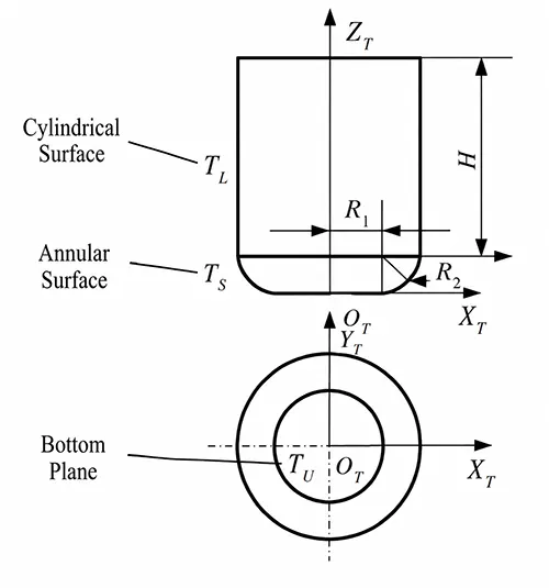
As shown in Figure 3, the structure of a ring milling cutter primarily consists of the following parts:
- a cylinder serving as the shank and providing support;
- a ring-shaped surface connected to the cylinder;
- and a smooth, circular cutting edge located below the ring-shaped surface.
Figure 4 illustrates the trajectory of the tool’s contact point as the tool moves across a free-form surface.
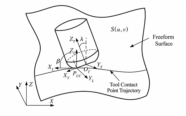
As shown in Figure 4, a specific tool contact point is identified along a given tool contact path; that is, the tool contact state at this point is defined by the tool’s position and orientation on the machining surface S(u, v).
This point is called the tool position point, which is a fixed point in the tool coordinate system during the machining process and must remain consistent at all times;
The other is the tool contact point, which is the point of contact between the tool and the designed surface during the machining process.
λ represents the tool rake angle, which is the angle by which a circular cutter rotates around an axis within the local coordinate system, with a range of [0, π/2];
As for β, it refers to the deflection angle. In this case, the milling cutter also rotates within the local coordinate system, with a range of [-π/2, π/2].
The sign of this parameter can be determined as follows: First, determine the direction of the cutter tip as projected onto the cutting plane where the cutter makes contact, thereby generating a projection line.
Then, observe the trajectory of the cutter tip to decide: if the line is seen as extending from the cutter tip to the right of the travel path, the lateral deviation is positive;
the opposite is also true—when the projection line falls to the left of the travel path, the lateral deviation is negative.
Summary
The cylindrical cutter combines the high efficiency of a flat cutting edge with the advantages of a spherical tip;
Due to its unique shape, it can sometimes be used as a hybrid of the two—that is, it possesses the characteristics of both, thereby offering enhanced performance and superior capabilities, particularly when processing complex-surfaced parts or intricate assemblies using multi-axis CNC machinery.
This type of machinery can perform tasks under computer control across five coordinate axes, meeting the current demand for fast and precise production and signaling that its use will become even more widespread.