
Impellers are core components of aircraft engines, gas turbines, and various compressors, and are widely used in the aerospace, marine, and automotive manufacturing industries.
Impeller Structure and Machining Challenges
Due to the complex structure of their blades, machining and manufacturing impellers is relatively difficult.
Impellers come in two structural types: monoblock and split. Split impellers allow for flexible blade replacement and are easier to machine, but they suffer from inconsistent machining precision and lack overall structural rigidity.
Traditional monoblock impeller manufacturing often employs sand casting, but this method suffers from low overall manufacturing precision.
Currently, manufacturers primarily produce monoblock impellers through metal cold cutting and 3D printing, but both methods involve considerable processing difficulty and provide insufficient strength.
The widespread adoption of multi-axis CNC machine tools has significantly reduced the difficulty of machining monoblock impellers.
As a result, manufacturers increasingly design impellers with a monoblock structure and produce them through multi-axis CNC machining.
This trend has increased attention to monoblock impeller machining and highlighted the practical value of research into its machining processes.
Research Gap in Monolithic Impeller Machining
However, most existing machining research relies on UG NX for programming and Vericut for machining simulation.
Researchers have conducted relatively little work on monolithic impeller machining with the SurfMill software platform.
This gap has limited the development of practical and reproducible machining processes for monolithic impellers.
Study Objective and Machining Approach
Building on existing research findings, this paper conducts a machining process study using a specific monolithic impeller part as the subject.
First, the process analyzes the basic structure and machining challenges of the impeller, selects a suitable machining plan, and prepares a machining process card.
Second, the process creates a 3D model of the impeller in the SurfMill software platform and generates NC machining code from the resulting toolpaths.
Finally, a multi-axis CNC machine tool performs the actual machining to verify the validity of the impeller machining process.
Manufacturing Process for Impellers
The process analysis considers both the required design accuracy and the manufacturing challenges of the impeller.
The machining process uses the “5-axis impeller machining” method provided by SurfMill 9.5 software to manufacture the impeller.
Based on this method, the process planner develops specific machining paths and prepares a detailed machining process sheet.
Process Analysis of the Impeller
Process analysis is a fundamental preparatory step for optimizing machining plans and writing machining programs.
It requires a thorough understanding of the impeller’s structural characteristics, machining requirements, and challenges to develop a reasonable machining process.
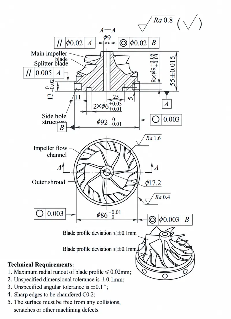
The impeller is made of TC4 titanium alloy. Its main structure is shown in Figure 1, with external dimensions of φ92 mm × 55 mm.
Key features include an axial φ9 mm central through-hole, eight circumferential φ8 × 11 mm side holes, and two φ6 × 5 mm locating pin holes on the bottom surface.
Specifically, the impeller section measures φ86 mm × 42 mm and consists of main blades and diverter blades arranged at equal circumferential intervals, as well as the curved impeller flow passage formed by these blades.
A further analysis of the part drawing reveals that the following technical challenges should be addressed when developing the machining process for the impeller section.
1) The impeller requires high machining precision.
For the outer contour of the impeller, the dimensional accuracy requirement is φ86 +0.00 mm; the shape and position tolerances are 0.003 mm for cylindricity and 0.003 mm for concentricity; and the surface roughness requirement is Ra 0.4 μm.
For the main blades and diverter blades of the impeller, the blade profile deviation must be ≤ ±0.1 mm, with a maximum deviation of ≤ 0.02 mm, and a surface roughness of Ra 1.6 μm.
The surface roughness of the R-corner at the blade root is extremely critical, requiring a surface roughness of Ra 0.8 μm, and the machining marks must be uniform.
2) The curvature of the impeller surfaces varies unevenly.
The main blades, diverter blades, and impeller flow passages are all free-form surfaces.
Differences in the radius of curvature at various locations result in uneven curvature variations across the surfaces, which severely limits the selection of tool types to avoid interference between the tool and the blades during machining.
3) The narrow space within the impeller flow passages makes root clearance machining difficult.
The intersecting circumferential layout of the main blades and diverter blades, combined with significant blade twist and minimal space between adjacent blades, results in narrow flow passages.
This restricts the tool’s range of motion, making it highly likely for the tool to experience overcutting against adjacent main or diverter blades during the cutting process.
During root clearance machining, the area of overlap with adjacent blades is greatest along the vertical direction of the tool axis, where the risk of overcutting is most severe.
Therefore, selecting a multi-axis CNC machine tool with reliable technical specifications and adopting reasonable machining methods are the primary process measures to prevent overcutting during root clearance.
4) It is difficult to ensure the machining quality of thin-walled blade structures.
Blades are thin-walled structures made of titanium alloy, which are prone to elastic deformation during machining;
Furthermore, the release of residual stresses caused by high-speed cutting can also lead to machining deformation of the blades.
Therefore, effectively controlling blade deformation is key to ensuring machining accuracy.
When developing the machining process, it is essential to reasonably plan the multiple-stage approach for roughing, semi-finishing, and finishing;
complete the aging treatment of the titanium alloy promptly before finishing;
allow for an appropriate finishing allowance;
and ensure that the cutting tools and machine tools meet requirements regarding clamping accuracy, dynamic balance, and rigidity.
Machining Plan for the Impeller
Process analysis shows that the significant blade twist and small R-angle at the blade root limit cutting tool clearance, increasing the risk of overcutting and interference.
The machining process therefore requires careful selection of the equipment, cutting tools, and machining methods to prevent these issues.
A three-axis CNC machine tool cannot meet the impeller machining requirements, so the process uses a five-axis CNC machine tool.
A five-axis CNC machine tool serves as the manufacturing platform for monolithic impellers.
Conventional programming methods struggle to meet the technical requirements of impeller machining programs, necessitating the use of CAM software to achieve automated programming.
SurfMill 9.5 software provides a feature-based “five-axis impeller machining” method, offering advantages such as minimal parameter settings, low programming complexity, and ease of operation.
It is evident that the “five-axis impeller machining” method based on the SurfMill 9.5 platform, when paired with a suitable five-axis CNC machine tool, can achieve the machining of monobloc impellers.
In addition, the impeller blades have a thin-walled structure, which makes them prone to machining challenges such as vibration and deformation during the machining process.
To prevent vibration and deformation, it is essential to carefully control the machining sequence, cutting tools, and machining parameters for the impeller.
Machining Sequence and Tool Selection
Several factors guide the machining sequence. These factors include the impeller’s structural characteristics, the type of multi-axis CNC machine tool, and the clamping and positioning methods.
Based on these factors, the machining sequence is determined as follows:
φ86mm step rough machining → φ86mm step finish machining → flow channel rough machining → semi-finish machining of main blades → semi-finish machining of diverter blades → finish machining of main blades → finish machining of diverter blades → flow channel finish machining → φ92mm outer diameter finishing → machining of 8 φ8mm circumferential side holes → chamfering of the upper and lower end faces of the base.
Several factors guide the selection of machining tools. These factors include tool–machine precision compatibility, machining requirements, flow channel space, and impeller material.
Based on these considerations, the process uses flat-bottom cutters, tapered ball-nose cutters, and large-head cutters.
Machining Parameter Optimization
The machining process focused on controlling impeller vibration and deformation when optimizing the machining parameters.
Based on machining experience, the process used several recommended sets of cutting parameters.
The researchers then used surface roughness as the optimization objective.
They applied an orthogonal experimental design to optimize the recommended machining parameters. The optimized results determined the machining parameters for each impeller machining process.
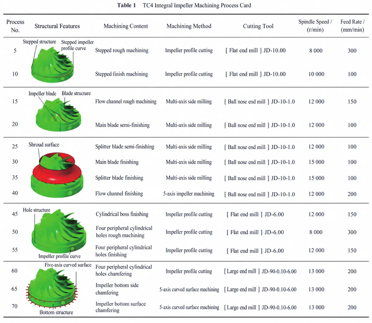
As detailed in Table 1, which lists the spindle speeds and feed rates.
A reasonable machining sequence, optimized machining parameters, and cutting tools compatible with the machine tool can effectively control the machining quality of the impeller.
These factors help maintain consistent machining results throughout the process.
Blank Preparation and Clamping
The part blank is shaped using a CNC lathe and a CNC milling machine.
During CNC lathe machining, leave a 0.5 mm machining allowance on one side of the φ92 mm outer circle.
Maintain a total height of 55 ± 0.015 mm. Keep the perpendicularity between the φ9 mm center through-hole and the bottom surface within φ0.02 mm.
Maintain a coaxiality of φ0.02 mm between the φ9 mm center through-hole and the φ92 mm outer circle.
The CNC milling machine machines two φ6 × 5 mm locating pin holes on the bottom surface. A turning center can also perform this operation simultaneously.
The bottom surface of the part blank and the two φ6 mm holes provide the positioning references. Bolts pass through the center through-hole to connect the part to the bottom fixture and secure the workpiece.
For batch production, the process uses a mandrel-and-nut clamping method.
Impeller Machining Process Sheet
Based on the above analysis, prepare an impeller machining process sheet.
The sheet covers the machining sequence, structural elements, machining details, machining methods, cutting tools, and cutting parameters. Table 1 presents the specific contents of the machining process sheet.
Multi-Axis CNC Machining of Impellers
Curved surface milling is a key aspect of blade machining, requiring consideration of machining methods, toolpaths, cutting parameters, and interference checks.
Multi-axis CNC machining of monoblock impellers mainly focuses on the main blades, diverter blades, and free-form flow-passage surfaces.
The process requires careful selection of machining methods and toolpaths. Parameter settings and interference checks also play a key role.
After selecting the cutting tools, the machining team performs a cutting interference check in SurfMill 9.5.
The check identifies potential interference caused by improper tool selection. It helps ensure safe machining throughout the process.
Rough Machining of Impeller Flow Channels
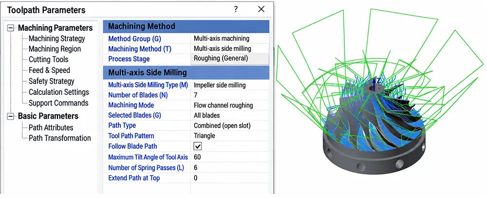
A multi-axis side milling module was used to rough-machine the impeller flow channels, with the spindle speed set to 12,000 r/min and the feed rate set to 150 mm/min.
The outer surfaces of the main blades and diverter blades serve as the machining surfaces for multi-axis side milling.
The enveloping surface and hub surface serve as constraints for the multi-axis side milling operation.
The process correctly marks seven sets of numerical values for the main blades and diverter blades.
The SurfMill 9.5 programming module then automatically rotates and optimizes the toolpaths for all seven sets.
Figure 2 shows the roughing toolpath for the impeller flow passages. The process reserves a 0.2 mm machining allowance on both the hub surface and the blade areas.
Impeller Flow Path Finishing
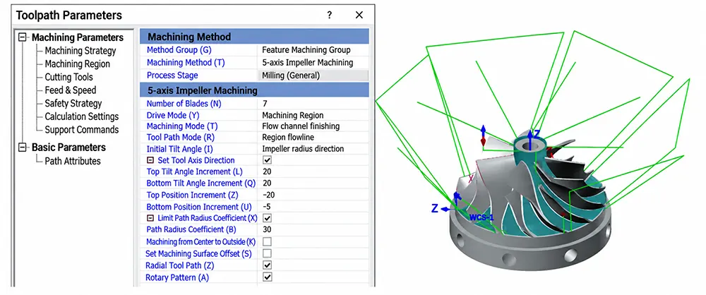
The five-axis impeller machining method is used to finish the flow channel of the TC4 monobloc impeller, with the spindle speed set to 12,000 r/min and the feed rate set to 200 mm/min.
The process requires special attention to the tool axis direction and deflection angle settings to prevent toolpath interference.
The top and bottom pitch angle increments are set to 20°, while the top and bottom azimuth angle increments are set to -20° and -5°, respectively.
The machining process simulates the generated five-axis impeller machining toolpath to verify the validity of the impeller flow channel finishing program.
Finally, the process performs an interference check to prevent collisions and overcutting. Figure 3 shows the toolpath for flow channel finishing.
Semi-Finishing and Finishing of Blades
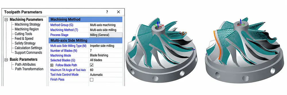
A side milling module is used to perform semi-finishing and finishing on the main blades and diverter blades of the impeller.
For multi-axis side milling of blades, it is important to note that burrs may form at the ends of the machined surfaces.
Removing these burrs can be difficult and may even affect local profile deviations at the blade edges.
To prevent burr formation, extended auxiliary machining surfaces must be added.
During semi-finishing, set the spindle speed to 12,000 r/min and the feed rate to 100 mm/min, leaving a machining allowance of 0.1 mm for both the main blades and the diverter blades.
For finishing, increase the spindle speed to 15,000 r/min, set the machining allowance to zero, and keep all other parameters unchanged.
The generated toolpaths for the semi-finishing and finishing of the blades are shown in Figure 4.
Machining Verification of the Impeller
The JDGR200 series machine tools were selected to perform actual machining on the impeller blades to verify the correctness of the machining process. Specific machine tool configuration and parameters:
Spindle model JD150S-20-HA50, maximum speed 20,000 r/min; CNC system JD50, which supports high motion efficiency and multiple motion profiles, allowing selection of different parameter profiles based on roughing and finishing requirements.
Additionally, the machine tool features an in-machine measurement system. The system precisely calibrates the rotary table center and machining coordinate system.
It maintains dynamic balance throughout the continuous impeller machining process.
After obtaining the toolpath source file for impeller machining, the process requires post-processing to convert it into NC code that the specific 5-axis CNC machine tool can recognize.
Therefore, the machining process uses SurfMill 9.5 functions, including machining simulation, toolpath overcut and interference checks, and machine tool simulation, to verify the reliability of the impeller machining process.
Actual Five-Axis Machining and Process Optimization
The JDGR200 five-axis high-speed machine tool performed the actual impeller machining.
During high-speed milling, the tool cut smoothly, the program ran well, and no collisions or overcutting occurred.
The entire machining process proceeded smoothly, with only the blade finishing operation requiring multiple adjustments.
Initially, the process used the same tool for both semi-finishing and finishing the blades.
After a single-pass finishing operation with a 0.1 mm sidewall machining allowance, the machining process produced vertical wrinkles on the sidewalls.
The process then reduced the sidewall finishing allowance to 0.05 mm, which reduced the visibility of the vertical wrinkles and improved surface quality.
Finally, the process replaced the finishing tool with one featuring better side-edge contour accuracy and controlled tool runout within 0.003 mm.
The revised process eliminated the vertical ripples on the sidewalls and significantly improved surface quality.
The total machining time for the blade was approximately 210 minutes, meeting the efficiency requirements for batch production.
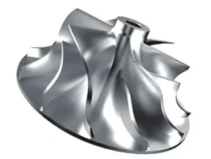
The actual results of the machined blades are shown in Figure 5.
Machining Accuracy and Inspection Results
Precision and surface roughness inspections of the blades revealed that the impeller’s outer contour diameter was φ86.004 mm, cylindricity was 0.002 mm, concentricity was 0.003 mm, and surface roughness was Ra 0.4 μm.
The blade profile deviation of the impeller blades was -0.003 mm, with a range of 0.018 mm, and a surface roughness of Ra 0.8 μm.
The surface roughness of the R-corner at the blade root was Ra 0.8 μm, and the tool marks were clearly visible and uniform upon visual inspection.
The inspection results confirm that all technical parameters of the machined impeller blades meet the design requirements.
The results verify the rationality of the impeller machining process and the correctness of the machining program.
Conclusion
1) The TC4 monolithic impeller presents several machining challenges.
High machining precision is essential. Surface curvature varies unevenly. Narrow flow channels make root clearance difficult. The thin-walled blades also require careful machining.
Two technical approaches address these challenges. The semi-finishing process machines the flow channels first, followed by the blades, including the main blades and diverter blades.
The finishing process reverses the sequence, machining the blades first and the flow channels second.
2) “Five-axis impeller machining and multi-axis side milling” are machining methods specifically designed for monobloc impellers;
Selecting appropriate cutting tools, creating suitable inspection geometries, and rationally planning toolpaths are key to machining this type of monobloc impeller.
3) SurfMill 9.5 provides various machining modules, machining simulation, toolpath overcut checks, and in-machine inspection features.
These features help address key challenges in monolithic impeller machining. Blade distortion can be significant, machining space can be limited, and tool interference and collisions can occur.