
Technical Requirements and Cutting Specifications
After turning, some surfaces of bearing rings do not undergo subsequent grinding operations (such as chamfers, oil grooves, stop grooves, dust-proof grooves, and small shoulders);
the dimensions and surface quality of these surfaces must directly meet the requirements for the finished product.
For surfaces that require grinding, reasonable parameters should be adopted as much as possible—while ensuring that heat treatment and grinding conditions are met—to facilitate subsequent processing steps.
Four Categories of Technical Requirements
Dimensional Accuracy: Ring width B and height T, inner diameter d, outer diameter D, groove diameter, groove radius of curvature, width of double-row tapered roller bearings, etc.;
Geometric Accuracy: End face straightness/curvature, variation in inner and outer diameters within a single plane (roundness), generatrix straightness, etc.;
Positional Accuracy: Width variation, parallelism of the groove centerline to the reference end face, runout of inner and outer diameters, groove position, thickness variation Ki/Ke, etc.;
Surface Quality: Appearance defects (rust, burn marks, grinding cracks, black skin, magnetic defects, scratches, etc.) and surface roughness.
Turning Allowance and Tolerances
The turning allowance refers to the material left after turning for grinding, while tolerances are the permissible deviations in turning.
Companies establish “Standards for Turning Allowances and Tolerances” and dynamically adjust them in response to changes in production conditions and technological advancements.
The main factors affecting turning allowances and tolerances include:
- Product structure, shape, and dimensions;
- Material type and blank quality;
- the technical condition of turning equipment and cutting tools;
- the degree of deformation resulting from heat treatment of the rings and the depth of the decarburization layer;
- the technical condition of grinding equipment and tools;
- the technical proficiency of production workers.
Principles of Stock Removal Control
The smaller the stock removal tolerance, the higher the grinding productivity;
However, excessively small stock removal can increase the scrap rate when heat-treatment deformation exceeds tolerances.
Conversely, excessively large stock removal results in low production efficiency and high material consumption.
The goal of establishing standards is to improve productivity and utilization while ensuring quality.
Surface Quality Requirements
The surface of turned parts must be free of black skin, cracks, dents, sharp edges, burrs, and dents.
The surface roughness of turned parts is generally Ra 2.5–4 μm; for assembly-grade circular chamfers, the requirement is Ra 2.5 μm.
Surface scratches or deep tool marks must not exceed half of the single-side allowance;
surfaces ground with a soft abrasive must not exhibit burn marks visible to the naked eye without acid washing.
Geometric and Positional Accuracy (Key Points of Internal Standards)
Geometric and positional accuracy in turning operations are typically governed by internal company standards. Common requirements are as follows:
Straightness: The straightness deviation of the outer diameter, inner diameter, and raceways shall not exceed 1/4 of the corresponding tolerance;
Width Variation: The width variation of the ring during rough turning shall not exceed the corresponding dimensional tolerance range;
When finishing is performed using an external reference face for positioning, it shall not exceed 1/2 of the width dimensional tolerance;
Parallelism of Grooves to the Reference Face (Groove Runout): Shall not exceed the groove position tolerance range;
Flatness of the Reference Face: Shall not exceed 1/4 of the width allowance;
Flatness of non-reference end faces: shall not exceed 1/2 of the width tolerance;
Roundness/Cylindricity: The variation in diameter after turning (cylindricity) shall not exceed 2/3 of the corresponding dimensional tolerance;
The cylindricity of the rough-turned inner diameter shall not exceed its tolerance range;
The roundness error of grooves and inner/outer diameters requiring grinding shall not exceed 1/2 of the corresponding diameter tolerance (not exceeding 1.5 times when the outer diameter is >200 mm);
Tapered Surfaces/Stop Grooves: Taper angle errors are typically expressed in units of length;
For external taper surfaces, △2β shall not exceed ±0.05 mm, and for internal taper surfaces, △2α shall not exceed 0.03 mm;
Diameter and width variations in stop grooves, dust-proof grooves, and similar features shall not exceed the corresponding tolerances.
Groove Turning: The Core Process That Determines Bearing Performance
The grooves are the working surfaces that bear the load during bearing operation, and they also serve as the raceways for the rolling elements.
The quality of the turned grooves directly determines the difficulty of subsequent groove grinding, as well as the vibration, noise, and service life of the final bearing.
The original text provides a very detailed description of the technical points involved in groove turning, which we will systematically summarize here.
Basic Requirements for Raceway Turning
When machining ball bearing raceways, the first step is to select appropriate spindle speed and feed rate based on the workpiece diameter.
Small and small-to-medium-sized raceways are typically turned in a single pass; medium and large raceways can be machined in roughing and finishing operations.
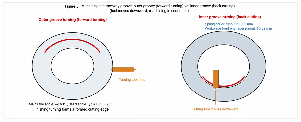
Finishing tools are usually ground to a pointed tip, with a main rake angle α₀ ≈ 3° and a front angle γ₀ = 10°–25°.
Differences Between External and Internal Groove Turning
External Groove Turning: The workpiece rotates, and the turning tool cuts from the outside toward the center to form the groove.
Since the workpiece’s outer circumference can serve as a positioning reference, clamping rigidity is high, and machining is relatively straightforward;
Internal Groove Turning: Space is limited, and chip evacuation is difficult.
The reverse cutting method is recommended—the tool cuts from the inside downward, directing the cutting force downward to ensure smooth chip evacuation and prevent chips from scratching the machined surface.
Fixture Alignment
Groove turning imposes strict requirements on fixture selection and adjustment.
Improper use of fixtures can lead to workpiece deformation, inadequate clamping, or slippage and chip breakage. Typical alignment requirements:
Runout of the spring-clamp transition disc ≤ 0.02 mm;
Runout of the front tapered surface of the housing ≤ 0.02 mm;
Machine the locating ring (commonly known as the “backstop”) flat to ensure reliable axial positioning.
“Coolant-Free” Hard Turning with Carbide and Ceramic Cutting Tools
When turning grooves or raceways with carbide turning tools or ceramic forming inserts, coolant is generally not used.
The heat generated during turning serves to heat and soften the metal layer in the cutting zone, thereby reducing cutting forces and minimizing vibration.
This method requires a good match between the tool material and geometric angles, as well as strict control of cutting parameters to prevent overheating and burn-through.
Tool Setting Methods and Adjustments for Changing Tool Models
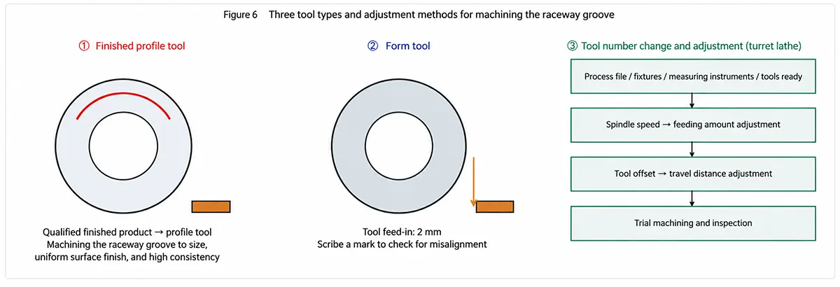
The accuracy of tool setting in groove turning directly determines the position, curvature, and dimensions of the groove. In practice, there are three commonly used tool setting methods:
Tool Setting on a Finished Part
This is the most common, simplest, and most reliable method. Procedure:
Load an acceptable product, and stop the tool holder at the end of its stroke;
Stop the feed first, then the spindle, and place the grooving tool into the tool holder slot;
Align the arc of the cutting edge with the groove on the acceptable products, and once the light passes evenly through the arc-shaped cutting edge, gently tighten the screw;
Retract the tool holder to its original position; after verifying the workpiece is qualified, tighten the screw fully, then make a slight adjustment to the feed rate to ensure smooth chip removal.
Tool Setting on a Blank
Applicable when there are no ready-made pass products available or when switching between batches of blanks:
First, install the turning tool in position and adjust the travel distance;
Position the tool holder approximately 2 mm from the workpiece’s machined surface;
Manually feed the tool to gently score a mark on the workpiece surface;
Check whether the center of the groove is misaligned; after aligning it, secure the tool, then slowly cut into the workpiece.
Model Changeover Adjustments (Machining)
When changing product models, system adjustments are required, which demand a high level of technical skill from the operator.
The process includes:
Preparing process documents, fixtures, measuring instruments, and cutting tools;
Installing and adjusting the fixtures;
Adjusting the lathe speed and feed rate;
Tool setting and adjusting the working stroke;
Calibrating the measuring instruments and performing a test cut on the first piece for inspection.
Common Defects and Inspection Methods
Turning is a high-precision process, but it is also prone to defects. Common issues and inspection methods are as follows:
Common Turning Defects
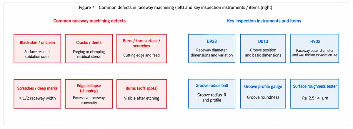
Black Skin/Incomplete Turning: Residual oxide scale on the surface, typically caused by defects in the blank or insufficient turning allowance;
Cracks, Dents: Caused by forging defects or excessive clamping stress;
Sharp Edges, Burrs, Dents: Caused by poor tool edge quality or impacts during handling;
Scratches/Deep Cuts: Caused by tool wear or poor chip evacuation; the depth must not exceed 1/2 of the single-side allowance;
Tool Chipping (Chip Breakage): A raised turning mark left in the groove after the tool tip chips off; the tool must be replaced immediately and the product isolated;
Soft Grinding Burn: Visible burn marks on the surface that can affect the quality of heat treatment.
Key Inspection Instruments
After turning the external groove, the following items must be inspected:
D923 instrument: Measure the external groove diameter and its variation;
D013 instrument: Measure the groove position dimensions and the parallelism of the groove to the reference end face;
H902 instrument: Measure the variation in groove thickness relative to the outer diameter surface (Ke);
Groove Curvature Sphere / Groove Profile Gauge: Measures the groove curvature radius R and groove roundness;
Surface Roughness Tester: Verifies that Ra falls within the range of 2.5–4 μm.
When turning grooves, special attention must be paid to controlling three core precision parameters:
groove position dimensions, groove curvature and shape errors, and the thickness variation between the groove diameter and the outer circle (or inner diameter).
When machining double grooves (or raceways), it is also necessary to control the center-to-center distance between grooves, the position of the groove centers relative to the end face, and the diameter difference between the two grooves.
Chip breakage must be addressed immediately; when a turning tool “chips off,” it leaves a raised turning mark in the raceway.
This not only damages the grinding wheel used for subsequent raceway grinding but may also result in the raceway surface not being ground to a circular shape, directly affecting bearing noise and service life.
Upon discovering chip breakage, the tool must be replaced immediately, and the machined products must be isolated and subjected to 100% inspection.
From Turning to Grinding: Getting Off to a Solid Start
Turning, heat treatment, and grinding are the three core processes in bearing ring manufacturing, and they influence one another:
Turning allows for heat treatment deformation: Since heat treatment deformation is inevitable, the turning allowance must be sufficient to accommodate the amount of deformation;
Turning provides a uniform allowance for grinding: An uneven allowance can lead to high localized grinding forces, excessive heat generation, and poor surface quality during grinding;
Turning ensures that non-ground surfaces are formed in a single operation: Features such as chamfers, oil grooves, and dust-proof grooves—which will not be machined again in subsequent processes—must meet specifications during the turning stage.
Therefore, turning is not merely “rough machining” or “shaping”; it is the first critical step in the chain of bearing quality formation.
Getting the first step right ensures that the subsequent processes—heat treatment, grinding, and superfinishing—can proceed smoothly, ultimately resulting in high-quality bearings with long service life and low noise.