
High-speed milling has become increasingly common in precision machining of shaft parts. However, higher cutting speeds create new surface quality challenges.
Under high-speed conditions, cutting heat, dynamic vibration, and material stress interact. These factors frequently cause surface defects and reduce component performance.
Therefore, studying surface quality control in high-speed milling has significant theoretical and practical value.
Quality Problems of Shaft Parts in High-Speed Milling
Surface Burns Caused by High-Speed Cutting Heat
During high-speed milling, the contact area between the tool and workpiece generates substantial cutting heat. When cutting speed exceeds a critical value, temperatures can reach 800–1,200°C.
This temperature range can exceed the phase transformation temperature of shaft materials. Cutting heat mainly originates from three sources.
Shear deformation on the tool rake face generates the primary heat source, accounting for 70%–80% of total heat. Friction between the tool flank and workpiece contributes another 15%–20%.
Friction between the rake face and chips generates the remaining 5%–10%. High-speed machining provides little time for heat conduction and dissipation.
As a result, local surface temperatures can rise rapidly. Temperatures above the critical limit may cause martensitic transformation or austenite grain coarsening.
These irreversible structural changes create a hard and brittle surface layer. Dark brown or blue-purple burn marks may appear macroscopically.
At the microscopic level, surface hardness increases abnormally, while residual tensile stress becomes concentrated. These changes can significantly reduce fatigue strength and service life.
Surface Ripple Defects Caused by High-Frequency Vibration
During high-speed milling, the spindle, tool, and workpiece clamping systems experience complex dynamic responses. High-frequency excitation forces drive these responses.
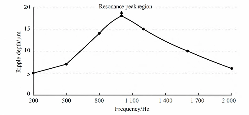
Resonance can occur when the excitation frequency approaches the system’s natural frequency. Several factors can act as major excitation sources.
These include spindle imbalance, periodic tooth engagement, and intermittent contact between the tool and workpiece. Their excitation frequencies usually range from 200 to 2,000 Hz.
Insufficient system stiffness or a low damping ratio can sharply increase vibration amplitude. The tool then moves periodically perpendicular to the feed direction.
This reciprocating displacement typically ranges from 5 to 20 μm. Such movement directly affects the regularity of the machined surface topography.
Vibration frequency shows a clear relationship with surface ripple depth. Ripple defects become most severe within specific frequency ranges.
Surface Cracking Caused by Residual Stress
High-speed milling produces intense plastic and elastic deformation between the tool and workpiece. These effects create a complex residual stress field.
High strain rates cause nonuniform plastic flow within the workpiece surface layer. Cutting heat also produces uneven thermal expansion and contraction.
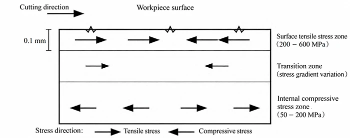
Together, these effects create a gradient of surface tensile stress and internal compressive stress. Surface tensile stress mainly occurs 0.01–0.10 mm below the surface.
The tensile stress typically ranges from 200 to 600 MPa. In contrast, the internal region remains under compressive stress.
Microcracks can initiate at stress concentration areas when surface tensile stress exceeds the material’s tensile strength. Shaft parts often experience alternating loads during service.
Residual tensile stress can combine with external stress and drive microcrack propagation. Cracks tend to extend along the maximum principal stress direction.
Surface cracks may reach depths of 0.005–0.050 mm and lengths of 0.1–2.0 mm. These defects significantly reduce fatigue strength and operational reliability.
Surface Scratches Caused by High-Speed Tool Wear
High-speed milling significantly increases the relative cutting speed between the tool and workpiece. Consequently, the cutting edge experiences severe mechanical and thermal loads.
When cutting speed exceeds 300 m/min, friction increases sharply at the rake and flank faces. The friction coefficient usually ranges from 0.6 to 0.8.
Intense frictional heat can raise the cutting-edge temperature to 800–1,000°C. Such conditions accelerate multiple tool wear mechanisms.
Diffusion, adhesive, and abrasive wear can occur simultaneously under high temperature and pressure. The cutting edge gradually loses sharpness and produces small wear particles.
A worn cutting edge becomes rough and irregular, losing its original geometric accuracy. Contact with the workpiece then produces uneven cutting pressure.
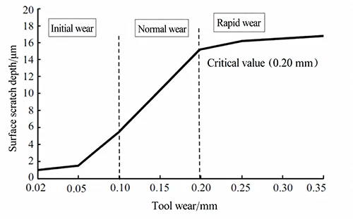
Surface scratch depth generally increases as tool wear progresses. Once tool wear exceeds the 0.20 mm critical value, scratch depth begins to stabilize.
However, the scratch depth may already approach 20 μm at this stage. This level of damage can seriously reduce surface quality.
Irregular cutting edges create grooves of different depths across the machined surface. Detached hard wear particles can also cause secondary surface damage.
Resulting scratches may measure 0.01–0.10 mm in width and 2–15 μm in depth.
Surface Quality Control Technologies for High-Speed Milling
Control Strategy for High-Speed Cutting Heat
A systematic thermal control strategy can address surface burns caused by cutting heat. Large heat generation remains the fundamental cause of these defects.
Therefore, an integrated system should control heat sources, optimize heat transfer, and monitor temperature.
Heat Source Control
Shear deformation on the rake face generates 70%–80% of total cutting heat. A 5°–15° rake angle can reduce shear stress and deformation heat.
A sharp cutting edge further supports this reduction. Friction between the tool flank and workpiece represents another important heat source.
TiAlN or AlCrN superhard coatings can reduce the friction coefficient from 0.6–0.8 to 0.3–0.5. A flank angle of 8°–12° also reduces frictional contact area.
Chip breakers and high-pressure cooling can control additional heat from rake-face and chip friction. Coolant pressure between 8 and 15 MPa helps evacuate chips quickly.
This approach prevents prolonged friction between the chip and tool surface.
Heat Transfer Optimization
Micro-jet technology can direct coolant precisely toward the contact area, increasing convective heat transfer. Tools with high thermal conductivity can also dissipate cutting heat rapidly.
Temperature Monitoring
An infrared temperature measurement system can provide real-time monitoring. The system should adjust machining parameters when surface temperature exceeds 800°C.
This approach helps prevent thermal damage, including martensitic transformation and austenite grain coarsening.
High-Frequency Vibration Suppression
High-frequency vibration results from interactions among multiple excitation sources. Resonance occurs when excitation frequency approaches the system’s natural frequency.
Consequently, vibration amplitude can rise sharply and create periodic ripple defects on the workpiece surface.
Vibration Source Control
Spindle imbalance represents a major excitation source during high-speed rotation. Precision dynamic balancing should limit imbalance to less than 0.5 g·mm.
High-precision bearings can improve spindle rotational accuracy to 0.002 mm or better. These measures reduce excitation intensity within the 200–2,000 Hz range.
Unequal tooth pitch or helix angle designs can disperse excitation frequencies from periodic tooth engagement. Variable feed strategies can also shift excitation away from natural frequencies.
System Optimization
The machine-tool-workpiece system requires dynamic optimization. Additional damping devices can increase the system damping ratio to 0.08–0.12.
Tuned mass dampers can provide vibration reduction at critical frequencies. Accelerometer-based systems can also monitor vibration in real time.
When vibration amplitude exceeds a defined threshold, machining parameters can change automatically. This adjustment helps the system avoid resonance regions.
Residual Stress Control in High-Speed Machining
Residual stress mainly results from high-strain-rate deformation combined with cutting heat. These factors cause nonuniform plastic flow and uneven thermal expansion.
The resulting stress field contains surface tensile stress and internal compressive stress.
Control of Stress Generation
Layered cutting divides the total cutting depth into multiple shallow passes. Each cutting depth should remain between 0.1 and 0.3 mm.
This method reduces plastic deformation during each pass and limits surface tensile stress concentration. Low-temperature cooling can address thermal stress caused by cutting heat.
Maintaining the workpiece surface at 200–300°C helps prevent additional thermal stress from rapid cooling.
Optimization of Stress Distribution
Cutting paths should first be optimized using spiral feed trajectories. This strategy prevents repeated cutting at the same location.
Variable cutting parameters can then reduce cutting forces during finishing. Surface residual tensile stress should remain below 60% of the material’s yield strength.
Finally, post-machining stress relief should use vibration aging or low-temperature tempering. Heat treatment at 200–250°C can release internal stress.
These measures can effectively suppress microcrack propagation at depths between 0.005 and 0.050 mm.
Conclusion
Surface quality control in high-speed milling is essential for improving machining accuracy and shaft performance. Major risks include burns, vibration ripples, residual-stress cracking, and tool-wear scratches.
A systematic approach combines three-source thermal control, multi-level vibration suppression, and layered cutting stress control. These measures address surface quality problems specific to high-speed milling.
The resulting control system provides technical support for precision machining of shaft parts. It also supports broader industrial application of high-speed milling technology.