
Frequent gearbox oil leakage in wind turbines endangers operation and raises maintenance costs.
To reduce oil leakage, the non-contact mechanical seal features irregular grooves that block oil and ensure adequate return chamber space.
However, the irregular groove structure significantly increases processing difficulty.
To machine the non-standard groove, the author presents a design example and proposes a machining process for the end face groove.
The proposed design aims to guide machining of similar structural components.
Analysis of the Structure and Machining Challenges of a Non-Standard Groove
Figure 1 shows a schematic diagram of the end face non-standard groove dimensions.
Figure 1 shows the non-standard groove with semi-closed and R-shaped structures, measuring 41 mm radial, 50 mm axial, and 28 mm opening.
The structure has a “pocket-like” shape with a small opening and large volume, preventing conventional tools from removing all material.
Using custom-made specialized tools increases both the production cycle and costs.
To tackle this, a customized tool adjusts the feed angle to machine Region 3, while Regions 1 and 2 use standard tools.
Figure 2 shows the schematic diagram of remaining material machining for the end face irregular groove.
Therefore, we must design a simple and reliable specialized tool to ensure the machining quality of the workpiece.

Figure 1: Schematic diagram of partial dimensions of the end face irregular groove
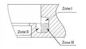
Figure 2: Schematic diagram of partial allowance machining of the end face irregular groove.
Processing Technology Analysis
Blank Selection
Gearboxes usually place mechanical seals on input or output covers, forming a labyrinth seal with oil throw and stop rings.
To reduce manufacturing costs, manufacturers often select ductile iron QT400 as the material.
Process Design
Machining Path Analysis
As shown in Figure 2, we divide the machining areas into Region 1, Region 2, and Region 3 based on machining sequence and difficulty.
For different regions, selecting the appropriate tools and feed methods is essential to achieve the optimal machining path.
Standard slotting tools can machine Regions 1 and 2.
As shown in Figure 1, Region 1 has a radial dimension of 25 mm and an axial dimension of 20 mm;
Region 2 has a radial dimension of 16 mm and an axial dimension of 30 mm.
Standard slotting tools commonly used on-site have a width of 5–8 mm;
For this machining operation, we selected a slotting tool plate with a width of 6 mm.
Treating regions 1 and 2 as conventional grooves for machining:
First, select a flat-edge slotting tool for high-feed machining;
For machining the inner radius R10, a pressure-type arc-shaped slotting tool is more suitable.
Additionally, select an arc tool with a radius smaller than R10.
In this case, we chose an R8 slotting tool.
For Area 3, the processing approach is as follows:
The cross-sectional opening dimensions determine the feed space, and material removal relies more on the tool’s feed angle.
Additionally, the feed angle is more influenced by the tool’s structural design.
Therefore, designing an appropriate tool structure and adjusting the feed angle to achieve processing is essential.
As shown in Figure 1, the irregular groove has a non-symmetrical structure.
If machined with a single feed angle, there will always be areas where machining is incomplete.
Therefore, we must design at least two tool structures to ensure feed angles overlap in certain areas, resolving this issue.
Setting the Machining Route
The machining path analysis shows that a slotting cutter is the main cutting tool for machining this irregular groove.
We perform aging after roughing and before finishing to release stress and ensure quality.
Selecting the right tool path improves surface quality and efficiency in groove machining.
For groove machining, the selection of machining tool paths plays a critical role in both surface quality and machining efficiency.
Traditional tool paths use radial feed to reach cutting depth, retract, move axially (within main cutting edge width), then repeat radial cutting.
We repeat this process until the entire area is machined.
In traditional machining tool paths, experts have analyzed their drawbacks and concluded that:
The first cut generates high force and lacks chip space, risking tool damage; later cuts load one edge, causing uneven wear.
The optimized toolpath uses small radial and axial feeds, repeating radial re-entry to reach the target width.
This addresses the issues of uneven tool wear and insufficient chip clearance space.
After analyzing the optimized toolpath, experts found that:
During axial feed, the toolpath cuts with the slot tool’s side edge, causing faster wear and vibration.
Additionally, if the slot bottom has varying heights, the toolpath requires multi-step operations in different regions.
They proposed a depth-layered method with 1 mm cuts, 2 mm retracts, and 1 mm shifts to keep the main edge engaged and improve efficiency.
Deep-layer machining uses thin layers and high feed rates, unlike traditional paths.
Therefore, the rough machining process adopts a deep-layer path using flat-edge pressure plate-type inserts.
During the finishing process, we selected arc-shaped inserts to machine along the slot cross-section contour.
Tool Design
The irregular slot’s base material is ductile iron QT400, and we can use ordinary slot cutting tools.
However, we must adjust the tool’s clamping method to accommodate its feed method.
A combined holder, plate, and pressure inserts ensure tool accuracy; only the holder clamp adjusts the feed angle.
The specific tool design is as follows.
- Modifying the tool holder best ensures feed angle safety, accuracy, and cutting rigidity.
In this case, the tool holder selected is the QZS2532 cutting tool holder.
- To reduce tooling costs, we select a commonly used cutting tool with a 6 mm effective width for the tool plate.
The inserts are selected as clamp-type inserts. The tool plate selected for this modification is the QEKS32N cutting tool plate.
Figures 3 and 4 show the schematic diagrams of the 65° and 40° modified tools.

Figure 3 65° modified tool schematic diagram
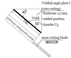
Figure 4 40° modified tool schematic diagram
- Map the feed angle to the holder with wire-cut welded plates for accurate angle and clamping; welding is the simplest method.
Precision-machine the welded tool holder’s clamping surfaces, ensuring right-angle perpendicularity for tool accuracy.
- Machining path analysis with a 6 mm tool width and 28 mm opening shows 40° and 65° feed angles meet requirements.
Figures 5–7 illustrate the machining and overlapping areas.

Figure 5 65° feed angle machining schematic diagram
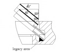
Figure 6 40° feed angle machining schematic diagram

The schematic diagram of the overlapping machining area is shown in Figure 7.
Machining Process Validation
Machining process analysis divides the irregular slot machining area into three parts.
We select air cooling for chip removal and use a vertical CNC lathe to machine the cast iron part.
The specific validation process is as follows.
We secure the part upright on the worktable with equal-height shims, aligning the groove axis parallel to the spindle axis.
Regions 1 and 2 use deep high-feed cutting, leaving a 1 mm allowance on the groove’s outer contour (see Figure 2).
Area 3 uses a specialized tool with depth-layered feed, leaving a 1 mm allowance on the slot’s inner contour (see Figures 3 and 4).
Internal stresses are eliminated through artificial aging or natural aging treatment, followed by subsequent finishing operations.
Regions 1 and 2 are finished using a R8 arc tool with a pressing plate.
The chamfered areas at the holes are processed using a small-angle diamond-shaped tool(see Figure 2).
The internal contour of Area 3 is finished using a R8 arc tool, completing the entire irregular groove machining process.
Two tools are mounted opposite the spindle, with feed angle adjusted to machine the groove in one operation.
The machined part is shown in Figure 8.
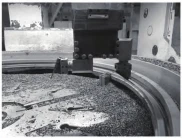
Figure 8: Actual machining diagram
We successfully machined the irregular slot with errors under 0.05 mm and surface roughness within Ra 6.3 using the process route and tool design.
Compared to custom tools, this method cuts costs, enables mass production, and ensures timely delivery.
Conclusion
This article illustrates the machining process, toolpath, design, and verification of an end face irregular slot.
The finished product shows this method yields economic benefits and guides machining of other irregular slots.