
Mechanical connections are essential for assembling modern aluminum vehicle bodies, providing reliable joining solutions for structural and functional components.
This article categorizes common connection methods—including self-piercing fasteners, riveting, blind riveting, welding, and threaded inserts—highlighting their mechanisms, advantages, limitations, and typical applications in automotive aluminum panels, castings, and extrusions.
Real-world examples illustrate each method, demonstrating how these fasteners and joining technologies ensure secure mounting of critical parts such as subframes, beams, harnesses, and reinforcement plates.
Mechanical Connection Category
Self-Piercing
Self-piercing bolts or nuts use cold-forming to penetrate sheet metal, creating a secure interlocking connection (Figures 1 and 2).
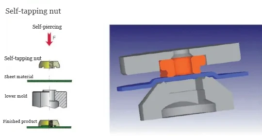
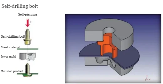
The manufacturing process of self-piercing fasteners comprises four stages: clamping, piercing, forming, and release.
Self-piercing fasteners withstand standard torque, require no pre-drilled holes, and seal well, but are costlier and suited only for aluminum panels under 2 mm.
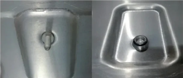
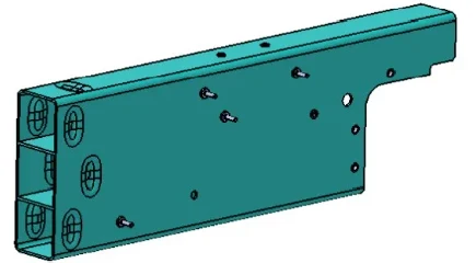
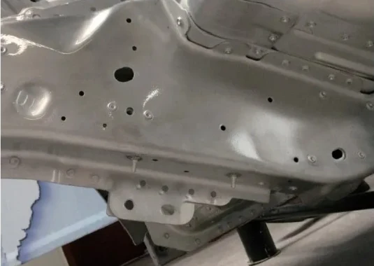
Figure 3 illustrates the application of self-piercing bolts in the front panel and floor areas of the Aion LX body.
Manufacturers widely apply self-piercing fasteners in aluminum stamped components for aluminum alloy vehicle bodies.
Riveting
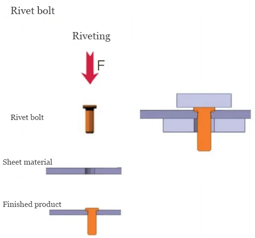
Riveting interlocks sheet metal via normal or radial structures, with tooth- and flange-interlocking rivets widely used in aluminum vehicle parts.
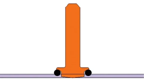
- Toothed interlocking rivets connect to sheet metal via a toothed base that forms an interference fit with the perforated cylinder (Figures 4 and 5).
The process involves three stages: component alignment, force application, and die closure forming.
These rivet fasteners feature a simple structure and lower cost, requiring only a flat surface for the lower die.
They provide limited ejection force and suit open cross-sections with low-precision points; engineers must exercise caution for critical hard points.
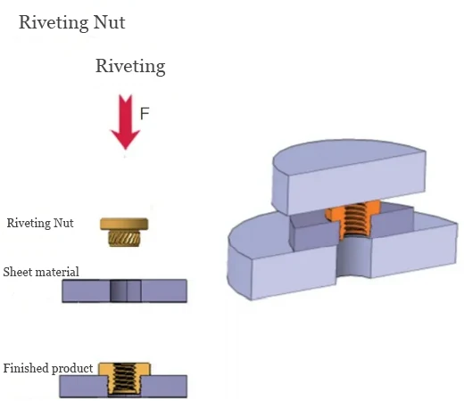
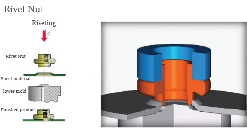
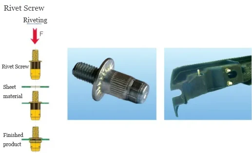
- Flanged interlocking fasteners join sheets as punch pressure bends the base flange to form the interlock (Figures 6 and 7).
The process comprises three stages: part alignment, force application, and mold closure forming.
These riveting fasteners offer strong ejection force and reliable connections but feature complex structures, higher costs, and require specific lower dies for forming.
Typically used for critical hard points or key mounting locations.
.webp)
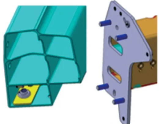
Figure 8 shows the application of press-fit rivet nuts and bolts on the sill and front bumper beam connection plates of the Aion V model.
Press-fit standard fasteners can be widely applied to various aluminum alloy body components.
Blind Riveting
Blind riveting secures sheet metal by deforming and expanding the fastener head to clamp the flange surfaces.
Manufacturers widely use it for metal sheet and tubing fastening, especially in aluminum vehicle bodies (Figures 9 and 10).
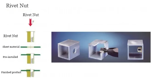
Operators perform the blind rivet process in four stages: automatic feeding, hole insertion, riveting, and reverse extraction (Figure 11).
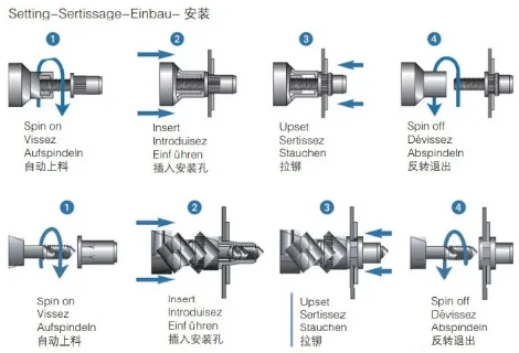
Blind riveting provides a simple, reliable, and easy-to-install one-way connection, but most rivet flanges protrude, preventing flush mounting.
Manufacturers use blind rivet bolts and nuts in aluminum bodies, castings, and thin parts to mount pipes, harnesses, and trims.
Figure 12 illustrates the application of blind rivet nuts and bolts in vehicles like the Model X.
Engineers widely use blind rivet fasteners in closed-section aluminum extrusions and open-section cast aluminum components.
Welding Technology
Aluminum Stud Welding
Aluminum stud welding joins the stud to the plate by arc ignition, surface melting, and pressure, as shown in Figure 13.
The aluminum stud welding process primarily consists of four stages: part loading, pre-tensioning, fusion, and withdrawal.
Aluminum stud welding is cheap and flexible but weaker than steel, mainly for fixing harnesses, pipes, and clamps to aluminum panels.
Figure 14 shows aluminum stud welding in vehicles like the Jaguar XE, with manufacturers using studs on stamped sheets.
Other Categories
Threaded Inserts
Threaded inserts engage aluminum castings with external threads and provide internal threads for connections, as shown in Figure 15.
For more than 40 years, threaded inserts have reliably enabled high-strength connections in low-strength metals.
These stainless steel inserts form internal threads in aluminum castings, with the shank breakable at the notch.
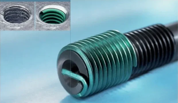
Threaded inserts are standard or self-locking. Standard ones use diamond-shaped coils to form internal threads usable on both sides.
Self-locking inserts share standard advantages and use a thread-locking zone to secure screws with polygonal coils.
Manufacturers widely use thread inserts in cast aluminum to mount critical parts like chassis points, batteries, and bodies.
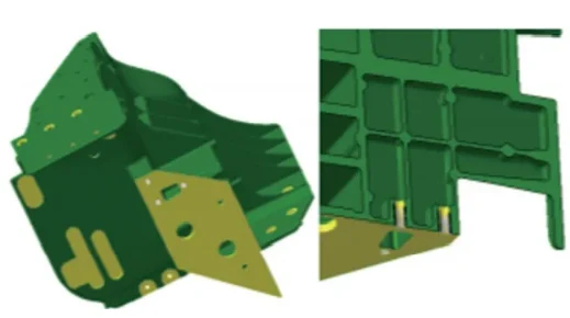
Figure 16 shows a thread insert on the NIO ES6 front beam joint, mounting the reinforcement plate between the joint and sill.
Aluminum Alloy Sleeve Nuts
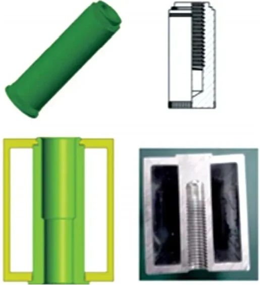
Aluminum alloy sleeve nuts are typically manufactured from 7-series special aluminum with internally formed threads, offering high connection strength.
Based on double thread length, they can sustain loads meeting PC10 grade requirements.
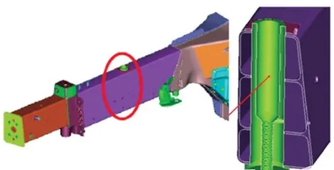
The sleeve employs a cold connection method to join both ends of the profile, enabling both ends to share the load. Its structural form is shown in Figure 17.
Aluminum alloy sleeve nuts offer advantages including reliable connections, high torque capacity, and simple assembly.
Disadvantages include higher cost and the need for coordinated application with specific profile beam cross-sectional dimensions.
Aluminum sleeve nuts secure critical points on aluminum body components like subframes, suspensions, motors, batteries, and seatbelt anchors.
Figure 18 shows an aluminum sleeve nut on the CT6 front beam, mounting the subframe.
Conclusion
In summary, mechanical connections play a vital role in assembling modern aluminum vehicle bodies, offering a range of solutions tailored to different structural and functional needs.
Self-piercing fasteners, various riveting methods, blind rivets, aluminum stud welding, threaded inserts, and sleeve nuts each provide unique advantages in terms of strength, ease of installation, and suitability for specific materials or components.
By understanding their mechanisms, limitations, and typical applications, manufacturers can select the optimal connection method to ensure secure mounting of critical parts such as subframes, beams, harnesses, and reinforcement plates.
Collectively, these mechanical joining technologies enhance vehicle structural integrity, assembly efficiency, and overall reliability.