
Technological advances in the automotive industry are driving the increasing complexity of component structural design, and the geometric features of irregularly shaped parts are becoming increasingly diverse.
Modern automotive irregularly shaped parts incorporate complex geometric shapes such as elliptical curves, parabolic contours, and multi-segment arcs, placing higher demands on CNC machining programming technology.
Traditional CNC programming, which defines shapes using point-by-point coordinates, requires extensive geometric calculations when dealing with complex contours, resulting in verbose program code and low development efficiency.
CNC macro programming technology is based on the concept of parametric programming.
Variable definition, mathematical operations, and logical control provide efficient programming solutions for machining complex, irregularly shaped parts.
Further research into these functions and their application to automotive irregularly shaped parts can provide practical value.
Overview of the Automotive Non-Standard Parts Machining Project
Analysis of the Characteristics of Automotive Non-Standard Parts
A certain automotive manufacturer has undertaken the task of mass-producing components for the chassis system of a new hybrid vehicle model.
The project includes typical irregular-shaped parts such as suspension control arms, subframe mounting brackets, and motor mounting brackets.
An annual production demand of 150,000 sets requires high machining precision and production efficiency.
These parts feature complex geometries and stringent performance requirements;
Their geometric characteristics include multi-dimensional surfaces, variable cross-sections, and asymmetric contours.
Most parts are made of high-strength steel, aluminum alloys, or composite materials, requiring excellent mechanical properties and fatigue strength.
In terms of structural design, irregularly shaped parts typically feature thin walls, local reinforcing ribs, and transition fillets, among other design elements, to achieve a balance between weight reduction and functionality.
Surface quality requirements for these parts are stringent, necessitating compliance with specific roughness standards and dimensional accuracy controls to ensure reliable assembly fits and overall product performance.
The design of the parts for this project integrates finite element analysis and topological optimization techniques, resulting in complex organic surfaces and irregular geometric features.
Technical Challenges in Machining Irregularly Shaped Parts
The machining of irregularly shaped parts presents multiple technical challenges, primarily related to geometric complexity and precision control.
Complex three-dimensional curved contours make toolpath planning difficult, and traditional linear interpolation methods often fail to meet the precision requirements for machining such surfaces.
During the material removal process, thin-walled structures are prone to deformation and vibration, which can affect machining accuracy and surface quality.
Clamping and positioning thus become critical technical challenges, as standard fixtures cannot provide reliable positioning references for irregularly shaped parts, necessitating the design of specialized fixture systems.
To meet the demands of small-batch, high-variety production, specialized fixtures typically employ modular, combinable designs or are equipped with flexible positioning elements;
However, these adjustments also significantly increase the difficulty of the process preparation phase and the associated costs.
Tool selection and cutting parameter optimization are complex tasks that require differentiated settings based on the geometric features and material properties of different areas.
Controlling thermal deformation during the machining process is challenging;
particularly under high-precision machining requirements, the impact of temperature changes on dimensional accuracy cannot be ignored, necessitating the adoption of appropriate cooling strategies and compensation measures.
The engineering project faced several key technical challenges during process implementation.
These challenges included complex multi-axis programming, difficult tool interference detection, and time-consuming machining path optimization.
Innovative Applications of CNC Macro Programming Technology
Methods for Designing Parametric Macros
Parametric macro design relies on variable definitions and mathematical expressions to establish a relationship between part geometry and program code, thereby achieving versatility and flexibility in machining programs.
By defining key dimensional parameters—such as part length, width, and arc radius—this method transforms complex coordinate calculations into parametric expressions.
The variable assignment system allows for rapid modification of part dimensions without the need to rewrite the entire program, significantly enhancing the program’s maintainability and modifiability.
During the implementation phase, parametric macro programming is often integrated with intelligent feature extraction algorithms;
The system autonomously captures the workpiece’s spatial geometry and connection structure data and converts them into parameter items and logical constraints within the code.
Iterative control and coordinate transformations enable rapid programming for standard parts with many repetitive structural units.
This approach significantly reduces redundant instructions.
The parametric modeling method also enables the linked updating of tolerance ranges and allowance thicknesses;
when production batches change or raw material properties fluctuate, the system can autonomously adjust cutting parameters to ensure a continuous and reliable machining process.
Conditional statements enable automatic selection of machining paths, executing corresponding machining strategies based on different parameter values.
The subroutine calling mechanism modularizes repetitive machining operations, reducing code redundancy and improving program execution efficiency.
The parametric design method establishes a mapping relationship between geometric features and machining parameters;
It describes the geometric features of complex surfaces through mathematical models to achieve parametric control of the program.
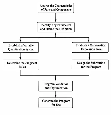
Figure 1 presents the parametric macro program design workflow.
The workflow covers the complete process from geometric analysis to program generation, including feature identification, parameter definition, algorithm design, and program verification.
Algorithm for Macro Programs in Complex Contour Machining
The algorithm for macro programs in complex contour machining establishes a conversion relationship between curve equations and CNC code based on mathematical models, thereby enabling the precise machining of complex geometric shapes.
For the machining of elliptical contours, parametric equations are used, with angle variables controlling the generation of the tool path. The equation for an ellipse is:
X=acos(θ)+X0 (1)
Y=bsin(θ)+Y0 (2)
In the formula, a and b represent the major and minor semi-axes of the ellipse, respectively; (X0, Y0) are the coordinates of the ellipse’s center; and θ is the parameter angle.
This algorithm uses a loop statement to control the incremental increase in the angle and, in combination with linear interpolation commands, achieves continuous machining of elliptical contours.
The setting of the loop step size requires a balance between machining efficiency and contour accuracy; if the step size is too large, the contour will appear polygonal, while if it is too small, machining efficiency will be compromised.
Parabolic and multi-segment circular arc contours employ similar parametric processing methods, describing geometric features through mathematical functions;
The macro program automatically calculates the coordinates of the trajectory points for each segment and generates the corresponding CNC commands.
Algorithm optimization includes self-adaptive step size adjustment and trajectory smoothing to ensure machining accuracy and surface quality.
Contour segmentation technology breaks down complex curves into multiple simple geometric segments, with each segment processed using the optimal interpolation method.
The error control algorithm ensures the geometric accuracy of the machining path through comprehensive control of chord height error and step size error.
Development of Multi-Operation Integrated Macro Programs
The development of multi-operation integrated macro programs unifies multiple operations—such as rough machining, semi-finishing, and finishing—within a single program framework to achieve automated control of the machining process.
The program structure employs a modular design approach, with each machining operation corresponding to an independent subroutine module.
Orderly switching between operations is achieved through calls from the main program.
The process parameter management system establishes a unified parameter library, covering key parameters such as cutting speed, feed rate, and cutting depth, and automatically retrieves the appropriate parameter combinations based on the machining process.
The tool management module enables automatic tool selection and replacement by retrieving information from a preset tool library according to machining requirements.
The traditional method of roughing, semi-finishing, and finishing across the entire mold surface using linear toolpaths suffers from efficiency issues.
Integrated macro programs effectively improve machining efficiency and automation by optimizing machining paths and process transitions.
Process transition control technology ensures smooth transitions between processes, avoiding accuracy losses caused by tool changes and repositioning.
The quality control module integrates online inspection functions to monitor machining quality in real time and make dynamic adjustments. Self-Adaptive Machining Strategy Selection:
Based on part features and material properties, the system automatically selects the optimal machining strategy and parameter combination to improve machining efficiency and ensure consistent quality.
Macro Program Adaptive Control Technology
Macro program adaptive control technology enables intelligent control of the machining process by dynamically adjusting cutting parameters and tool paths through real-time monitoring of machining status parameters.
This technology establishes a correlation model between machining parameters and part quality, and automatically optimizes cutting speed and feed rate based on material properties, tool wear, and machining accuracy requirements.
The cutting force monitoring system collects cutting force signals in real time during the machining process;
Once abnormal fluctuations are detected, it automatically adjusts cutting parameters to prevent tool damage and workpiece deformation.
The temperature compensation algorithm is based on thermal deformation theory and automatically corrects coordinate positions according to temperature changes during the machining process, thereby ensuring the stability of machining accuracy.
Vibration monitoring and suppression technology suppresses vibration by automatically adjusting machining parameters through real-time monitoring of the machine tool’s vibration status.
The tool wear prediction algorithm is based on the fusion of multiple parameters, such as cutting force, temperature, and vibration, enabling intelligent assessment of tool condition and predictive maintenance.
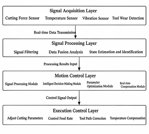
The adaptive control system architecture shown in Figure 2 illustrates the complete process of sensor signal acquisition, parameter processing, and control execution, thereby enabling closed-loop control of the machining process.
Evaluation and Analysis of Application Results
Testing the Effectiveness of Programming Efficiency Improvements
Macro programming technology demonstrates significant efficiency advantages in the programming of irregularly shaped automotive parts.
Traditional manual programming requires point-by-point coordinate calculations and the writing of large amounts of repetitive code when handling complex contours, whereas macro programming achieves the goal of “write once, use many times” through parametric definitions.
In the programming task for a suspension arm bracket, the traditional method required writing 1,850 lines of code and took approximately 15 hours.
In contrast, the macro method required only 380 lines of core code, reducing programming time to 4 hours—a 73.3% increase in efficiency.
During the development of the machining program for the elliptical contour of the steering knuckle connector, macro programming technology automatically generated trajectory points using parametric equations, thereby avoiding the tedious process of manual calculation.
As shown in Table 1, the results of the programming efficiency comparison analysis indicate that the average programming efficiency for three typical irregularly shaped parts increased by 72.0%, and the number of lines of code was reduced by approximately 80%.
In terms of program modification efficiency, when part dimensions change, traditional programs require modifying all relevant coordinate points one by one, whereas macro programs can be updated simply by adjusting parameter values.
| Part Type | Traditional Programming Code Lines | Macro Program Code Lines | Traditional Programming Time / h | Macro Programming Time / h | Efficiency Improvement / % |
|---|---|---|---|---|---|
| Cantilever Arm Bracket | 1,850 | 380 | 15.0 | 4.0 | 73.3 |
| Rotary Joint Connector | 1,420 | 290 | 11.5 | 3.2 | 72.2 |
| Battery Pack Support Beam | 2,180 | 420 | 18.5 | 5.5 | 70.3 |
| Average | 1,817 | 363 | 15.0 | 4.2 | 72.0 |
Table 1. Programming Efficiency Comparison Analysis
Machining Accuracy Inspection and Analysis
CNC macro programming technology has demonstrated outstanding performance in controlling the machining accuracy of irregularly shaped parts, achieving high-precision machining goals through precise mathematical models and adaptive control algorithms.
Test results for the machining accuracy of elliptical contours show that the contour error controlled by macro programs is maintained within ±0.015 mm, representing a significant improvement compared to the ±0.028 mm error achieved with traditional programming methods.
When machining complex surfaces, the macro program effectively eliminates abrupt changes and discontinuities in the machining path through dense trajectory point generation and smooth interpolation processing.
To address the problem of localized material folding in the multi-station cold heading production of special-shaped nuts for the automotive industry, similar precision control technologies apply to complex forming processes.
In terms of surface roughness, the macro program optimizes cutting parameters and tool paths, stabilizing the Ra value of the machined surface within the range of 1.2 to 1.6 μm.
Long-term production statistics show that the pass rate for parts machined using macro programming reaches 98.5%, a significant improvement over the 94.2% pass rate achieved with traditional programming.
In terms of machining consistency, dimensional deviations for parts within the same batch are controlled within a range of ±0.008 mm, meeting high-precision assembly requirements.
Program Maintainability Evaluation Metrics
Macro programs offer significant advantages in terms of maintainability; their modular program structure and parameterized control greatly reduce maintenance difficulty and costs.
In terms of code readability, macro programs rely on variable names and a system of comments to establish a clear logical structure, enabling technicians to quickly understand program functionality and key modification points.
Table 2 compares program maintainability metrics. Macro programs improved code readability scores by 48.3% and reduced parameter modification time by 86.1%.
The program reuse rate reached 85%.
In terms of error diagnosis capabilities, the structured design of macro programs makes debugging more efficient, and modular testing allows for rapid identification of problem locations.
Training cost analysis indicates that the learning curve for technical personnel to master macro programming methods is approximately 40% shorter than that of traditional methods, reducing investment in staff training, overall maintenance costs have decreased by 58.0%.
Macro programs have significantly improved version management efficiency, standardized program updates and version control, and reduced the incidence of human error.
| Evaluation Metric | Traditional Programming | Macro Programming | Improvement / % |
|---|---|---|---|
| Code Readability Score (1–10) | 5.8 | 8.6 | +48.3 |
| Parameter Modification Time / min | 180 | 25 | −86.1 |
| Error Diagnosis Time / min | 45 | 12 | −73.3 |
| Program Reusability / % | 35 | 85 | +142.9 |
| Training Cycle / days | 15 | 9 | −40.0 |
| Maintenance Cost Index | 1.00 | 0.42 | −58.0 |
Table 2. Comparison of Program Maintainability Metrics
Conclusion
CNC macro programming technology has demonstrated significant technical advantages and practical value in the machining of irregularly shaped automotive parts.
By utilizing a parametric programming model, this technology effectively addresses the efficiency bottlenecks and precision control challenges associated with traditional programming methods when handling complex geometric shapes.
The introduction of macro programming algorithms has enabled the standardization and automation of complex contour machining, while the integrated development of multiple processes has enhanced the overall coordination of production systems.
As the automotive manufacturing industry continues to evolve toward intelligent manufacturing, CNC macro programming technology will undergo in-depth integration with advanced technologies, forming more intelligent machining control systems that provide a technical foundation for automotive manufacturers to reduce production costs and improve product quality.