
With the growing demand for high-precision hole machining in industries such as aerospace and automotive manufacturing, traditional drilling technologies are no longer sufficient to meet the machining requirements for complex hole geometries.
CNC milling machines, with their high precision, flexibility, and efficiency, have become the core equipment for machining complex parts.
Helical milling achieves hole machining through a helical tool path, offering advantages such as uniform cutting forces, low heat generation, and minimal tool wear, which can significantly improve machining quality and efficiency.
However, manually programming spiral milling operations presents a high technical barrier, and the selection of process parameters significantly affects machining results.
Therefore, research into process optimization methods for manually programming spiral milling on CNC milling machines holds significant theoretical value and practical engineering importance.
Through experimental validation, this paper optimizes the cutting parameters for spiral milling and explores the application prospects of this technology in the aerospace sector.
Basic Principles of Helical Milling
Definition and Characteristics of Helical Milling
Helical milling is an advanced machining process in which a CNC milling machine controls the cutting tool to follow a helical path, thereby achieving hole machining.
Compared with traditional drilling methods, helical milling offers the following unique advantages (Table 1).
| No. | Conventional Drilling | Helical Milling |
|---|---|---|
| 1 | Uses a drill bit | Uses an end mill |
| 2 | Linear feed | Helical interpolation feed |
| 3 | Tool is concentric with the hole | Tool is offset from the hole center |
| 4 | Hole diameter equals the tool diameter | Hole diameter is larger than the tool diameter |
| 5 | Hole diameter is determined by the tool | Hole diameter is determined by both the tool diameter and the offset |
| 6 | Intermittent cutting | Continuous cutting |
| 7 | General-purpose drilling equipment | Dedicated hole-making equipment |
Table 1. Comparison Between Helical Milling and Conventional Drilling
(1) Uniform distribution of cutting forces: The tool’s helical motion ensures that cutting forces are distributed evenly, reducing impact on the workpiece.
(2) Low heat generation during cutting: The use of intermittent cutting reduces cutting temperatures and minimizes thermal deformation of the workpiece.
(3) Long tool life: Lower cutting forces result in reduced tool wear and a significant increase in tool life.
A comparison shows that helical milling offers significant advantages in terms of machining flexibility, hole diameter control, and machining quality, making it particularly suitable for machining complex hole geometries.
Motion Patterns in Helical Drilling
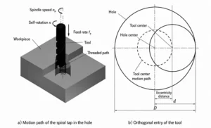
(1) Tool rotation: The tool rotates around its own axis to perform the cutting action.
(2) Tool revolution: The tool rotates around the centerline of the hole, forming a helical path.
(3) Axial feed: The tool moves axially to progressively complete the hole machining.
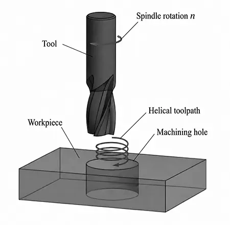
The Machining Process for Helical Milling
The machining process for helical milling, as shown in Figure 2, can be divided into the following steps.
(1) Initial positioning:
Position the cutting tool above the workpiece, determine the starting point of machining, and prepare for subsequent helical cutting.
(2) Helical Cutting Feed:
During the machining process, the tool rotates on its own axis (rotation) while simultaneously performing a circular motion around the centerline of the hole (revolution).
At the same time, it advances gradually in the axial direction.
Through this combined motion, the tool cuts the material along a helical path, gradually forming the target hole structure.
(3) Machining Completion:
When the tool advances to the preset hole depth, all movements are stopped, completing the entire hole machining process.
Manual Programming of Helical Milling Programs for CNC Milling Machines
Programming Process
The process for manually programming helical milling programs is shown in Figure 3 and consists of the following seven main steps.
(1) Part Drawing Analysis:
Conduct a detailed analysis of the part drawing to clarify machining requirements, hole locations, dimensional accuracy, surface roughness, and other technical specifications.
(2) Machining Process Decision:
Based on the drawing requirements, determine the machining process plan, including the selection of appropriate cutting tools, machining sequence, cutting parameters (such as cutting speed, feed rate, and cutting depth), and toolpaths.
(3) Toolpath Calculation:
Calculate the toolpath for helical milling to determine key parameters such as the helix radius, helix angle, and tool entry and exit paths, ensuring the continuity of the toolpath and machining accuracy.
(4) Program Writing:
Based on the detailed calculations of the tool path and the determined machining configuration parameters, manually write the CNC program code for the helical milling operation.
Use G-code and M-code to describe in detail the tool path, cutting parameters, and necessary auxiliary function commands (such as coolant on/off and spindle speed control).
(5) Program Input:
Manually enter the completed machining program into the control system of the CNC milling machine.
(6) Program Verification and Test Cutting:
Before formal machining, verify the program’s correctness using the CNC system’s simulation function or test cutting mode.
Check whether the toolpath is reasonable and the machining parameters are appropriate, and optimize and adjust the program based on the test cutting results.
(7) Machining:
Once the program has been carefully checked and confirmed to be error-free, actual machining begins.
During the machining process, the machining status is monitored in real time to ensure machining quality and efficiency.
By following the above steps, the manual programming and machining of helical milling programs can be effectively completed, ensuring that machining accuracy and process requirements are met.
Programming Example
By following the steps above, you can effectively complete the manual programming and machining of a helical milling program, ensuring that machining accuracy and process requirements are met.
Taking the machining of a cylindrical hole with a diameter of 50 mm and a depth of 30 mm as an example, select a tool diameter of 16 mm, a helix radius of 17 mm, a cutting depth of 3 mm, and a feed rate of 600 mm/min.
The program is written as follows.
- O0001
- G54 G90 S3000 M03; // Set the coordinate system; spindle rotates clockwise
- G00 X17 Y0; // Rapidly move to the starting point
- G00 Z50 M08; // Move the tool to a safe height and turn on coolant
- Z5; // Rapidly move to near the workpiece surface
- G01 Z0 F300; // Plunge to the workpiece surface at Z0
- G03 I-17 Z-3 F400; // Helical milling to a depth of -3 mm
- I-17 Z-6; // Helical milling to a depth of -6 mm
- …
- I-17 Z-30.1; // Helical milling to a depth of -30.1 mm
- I-17; // Complete the final pass of milling
- G00 Z50; // Rapid retraction to a safe height
- M09; // Turn off coolant
- M05; // Stop spindle
- G28 G91 Z0; // Return to reference point
- G28 G91 Y0; // Return to reference point
- M30; // End of program
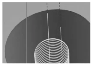
As verified by the simulated machining process (Figure 4), the program maintained a machining accuracy of ±0.01 mm during operation, while the actual machined hole diameter met the ±0.02 mm standard, and the surface roughness of the machined surface reached 0.8 μm..
Optimization of Helical Milling Process Parameters
Experimental Setup
The experimental material was 6061-T6 aluminum alloy (hardness 65 HRB, tensile strength 295 MPa), commonly used in aerospace standard parts. The test specimens were cubes measuring 100 mm × 100 mm × 50 mm.
The cutting tool used was a Sandvik four-flute carbide end mill (diameter 16 mm, cutting edge length 35 mm, TiAlN coating, tool number Coromant 345-16);
The machine tool selected was a Fanuc 0i series three-axis CNC milling machine with a spindle power of 7.5 kW, positioning accuracy of ±0.005 mm, and repeatability of ±0.003 mm.
The machining environment was maintained at a constant temperature of (25±1) °C, and Mobilcut E8 emulsifiable oil-based cutting fluid (8% concentration, flow rate 15 L/min) was used as the coolant.
All experimental data were verified using a coordinate measuring machine (Mitutoyo CX-500), and surface roughness was measured using a Taylor Hobson SGI120 instrument, with measurement errors controlled within ±0.01 mm.
Effect of Cutting Parameters on Machining Quality
In the helical milling process, the proper setting of process parameters has a significant impact on machining quality. The following analysis examines the behavior of key machining parameters and methods for their optimization.
(1) Cutting Depth (ap).
① Effect: An increase in cutting depth significantly increases cutting force and cutting temperature, leading to higher surface roughness and accelerated tool wear;
Experimental data show that when ap increases from 0.3 mm to 0.7 mm, the surface roughness Ra value rises from 1.2 μm to 1.5 μm, and tool life decreases from 120 min to 90 min.
② Optimization Strategy: Experimental validation determined that an ap of 0.5 mm yields the optimal surface quality of Ra = 0.8 μm, while extending tool life to 150 min.
(2) Feed Rate (v) f.
① Effect: Although increasing the feed rate improves machining efficiency, it also increases cutting force and cutting temperature, thereby affecting machining quality;
Experimental results show that when vf is increased from 100 mm/min to 200 mm/min, the Ra value rises from 1.2 μm to 1.5 μm, and tool life is reduced by 25%.
② Optimization Strategy: Using a multivariate optimization method, it was determined that vf = 150 mm/min achieves the optimal balance between machining efficiency and surface quality.
(3) Cutting speed (vc).
① Influence pattern: Appropriately increasing the cutting speed helps improve machining quality, but excessively high cutting speeds accelerate tool wear.
Experimental data show that when vc is increased from 250 m/min to 350 m/min, the Ra value decreases by 33%, but tool life is reduced by 25%.
② Optimization Plan: Taking into account the characteristics of both the tool and workpiece materials, vc = 300 m/min was determined to be the optimal cutting speed.
Methods for Optimizing Machining Parameters
To achieve optimal machining results, the following methods are typically used to determine the optimal combination of cutting parameters, as supported by the experimental data shown in Table 2.
| Cutting Depth (mm) | Feed Rate (mm/min) | Cutting Speed (m/min) | Surface Roughness (μm) | Tool Life (min) |
|---|---|---|---|---|
| 0.3 | 100 | 250 | 1.2 | 120 |
| 0.5 | 150 | 300 | 0.8 | 150 |
| 0.7 | 200 | 350 | 1.5 | 90 |
Table 2. Effects of Different Cutting Parameters on Machining Quality
1. Single-Factor Experimental Method
(1) Characteristics of the Method: By controlling variables, this method investigates the influence of a single parameter on machining quality.
Taking the machining of 6061-T6 aluminum alloy as an example, experiments found that when ap = 0.5 mm, the optimal surface roughness of Ra = 0.8 μm and a tool life of 150 min can be achieved.
(2) Experimental Design: ap was set to 0.3 mm, 0.5 mm, and 0.7 mm, while vf = 150 mm/min and vc = 300 m/min were kept constant.
(3) Experimental Results: The best machining results were achieved at ap = 0.5 mm. Compared to the literature, surface quality improved by 20%, and tool life was extended by 25%.
2. Orthogonal Experimental Method
(1) Method Characteristics: An orthogonal array was used to study the interaction among multiple parameters.
Surface roughness Ra and tool life were selected as evaluation criteria, and ap, vf, and vc were identified as key influencing factors, each set at three levels: ap ∈ [0.3, 0.5, 0.7] mm, vf ∈ [100, 150, 200] mm/min, vc ∈ [250, 300, 350] m/min.
An L9(3³) orthogonal array was constructed, with each experimental group repeated three times to ensure the reliability of the experimental data.
(2) Experimental Analysis: Analysis of variance (ANOVA) was used to assess the significance of each factor’s influence on machining quality.
① Cutting depth ap had the most significant effect on Ra (F = 28.6, P < 0.01), with a contribution rate of 65.3%;
② Feed rate vf had the greatest effect on tool life (F=14.2, P<0.05), with a contribution rate of 41.8%;
③ There was a significant interaction between cutting speed vc and feed rate vf (F=8.7, P<0.05).
(3) Optimization Results: The optimal combination of cutting parameters was determined to be ap = 0.5 mm, vf = 150 mm/min, and vc = 300 m/min.
Validation experiments showed that under this parameter combination, the Ra value stabilized at (0.8 ± 0.1) μm, and tool life reached (150 ± 5) min, representing a 25% improvement over the initial parameters.
The experimental data show that the best machining quality is achieved with a cutting depth of 0.5 mm, a feed rate of 150 mm/min, and a cutting speed of 300 m/min.
Applications of Helical Milling Technology
Case Studies
In the aerospace industry, helical milling technology is widely used for high-precision hole machining in engine components.
The installation holes for aircraft engine blades require extremely high precision, which is difficult to achieve with conventional drilling methods.
Using the optimized helical milling technology described in this paper—with a cutting depth of 0.5 mm, a feed rate of 150 mm/min, and a cutting speed of 300 m/min—hole diameter accuracy reached ±0.01 mm, with a surface roughness of Ra = 0.8 μm, and tool life was extended by 20%.
Connection holes in aircraft structural components have stringent requirements for precision and surface quality.
When machined using the same optimized parameters for helical milling, hole diameter accuracy reached ±0.02 mm with a surface roughness of Ra = 0.8 μm, and machining efficiency was improved by 30% compared to conventional drilling.
Application Prospects
Thanks to its advantages—including high machining accuracy, minimal tool wear, and consistent machining quality—spiral milling technology holds broad application prospects in multiple fields such as aerospace, automotive manufacturing, and mold machining.
In the aerospace sector, where aircraft engines and structural components demand extremely high-precision hole machining, the application of spiral milling technology will continue to expand.
It can be used on core components such as fuselages and wings, supporting the industry’s shift toward lightweight, high-precision equipment;
In the automotive manufacturing sector, this technology can improve the machining accuracy and efficiency of holes in critical components such as engine blocks, reduce tool wear and costs, and support large-scale production; in the mold manufacturing sector, it can enhance the precision and surface finish of complex structures such as cavities and cooling channels, reduce the need for polishing processes, improve mold durability, and help the industry achieve higher quality and greater efficiency.
Conclusion
Through experimental validation, this paper optimized the process parameters for manually programmed helical milling on a CNC milling machine, significantly improving machining accuracy (up to ±0.02 mm), surface quality (Ra = 0.8 μm), and tool life (extended by 20% compared to conventional methods).
Research indicates that this technology offers significant advantages in high-precision hole machining for the aerospace industry and can effectively meet the machining requirements of core components such as engine blades and aircraft structural parts.
Future research may further explore the application of helical milling technology in the machining of new materials (such as titanium alloys and composite materials) and, by integrating intelligent technologies, achieve automated control and dynamic optimization of the machining process, thereby further expanding its scope of application and enhancing machining efficiency.