A fiber optic connector (see Figure 1) is an optical device used to establish a detachable (movable) connection between two or more optical fibers, primarily for interfacing fiber to fiber.
It ensures minimal loss of optical signals during transmission while guaranteeing connection reliability and stability.
Fiber optic connectors are widely used in data centers, long-distance lines, home broadband, and industrial automation due to advances in fiber optic technology.
Miniaturization of fiber optic connectors has increased, raising demands on molds that often use precision small shafts for forming.
Micro-shafts (~ϕ0.2 mm, tips ~ϕ0.1 mm) exceed traditional grinder capabilities, and even in the U.S. and Japan, specialized chucks for such ultra-fine shafts are unavailable.

a——SC Connector ;b——LC Connector ;
c——ST Connector ;d——FC Connector;

This paper outlines the full process of preparing, grinding, and finishing precision small shafts for mold manufacturing.
Analysis of Precision Small Shaft Dimensions, Geometric Features, and Accuracy
Figure 2 shows a ϕ0.2 mm, 28.6 mm shaft with a 143:1 length-to-diameter ratio; its 0.01 mm straightness tolerance is critical.
The tip’s ϕ0.127 mm dimension and 0.005 mm coaxiality tolerance are key indicators for ensuring positional and dimensional accuracy.
The 0.2mm shoulder flat serves as the mounting dimension for positioning, requiring special attention to symmetry.
Shaft and tip dimensions, critical for mold forming, require 0.002 mm tolerance, demanding precise processes to ensure accuracy.
This precision small shaft is exceptionally delicate compared to traditional shaft products. Surface roughness requirements for the shaft-to-bore fit must not be overlooked.
Manufacturing and Debugging
In specialized machine tools, support plates for centerless and step grinders usually exceed 0.5 mm; 0.3 mm is theoretically possible but rarely used.
Even a 0.3mm-thick support plate cannot achieve shaft shaft-end external grinding due to its thickness exceeding the shaft shaft-end dimension of ϕ0.2mm.
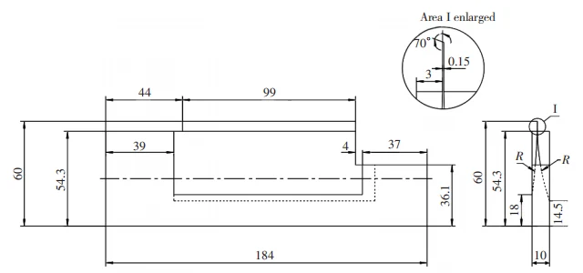
A support plate with a thickness less than 0.2mm is required to machine the 0.2mm shaft diameter.
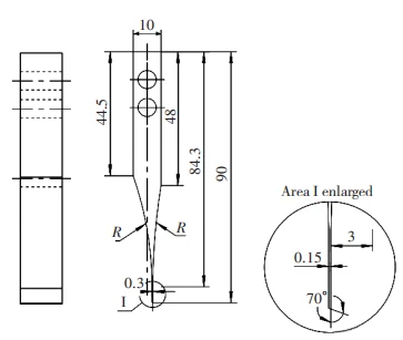
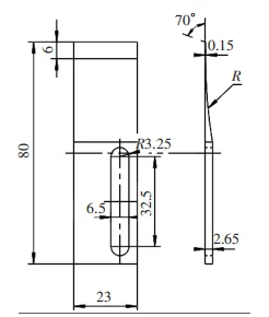
This necessitates custom fabrication—specifically, modifying existing thinner support plates and workpiece locators to the dimensions shown in Figure 3.
Only then can centerless and step grinders be used to machine both the shaft diameter and tip dimensions.
Centerless Grinder Modification with 0.15mm Support Plate.
Choose a 0.3 mm support plate and grind its 70° cutting edge to a flat surface, maintaining 0.01 mm straightness and Ra 0.1 μm roughness.
Grind the 0.15 mm carbide edge, control position accuracy, and measure thickness, noting front/back step differences.
Convert a 0.15mm workpiece locator for use on a centerless grinder (see Figure 4).
Modify a 0.4 mm centerless grinding backing plate, ensuring the carbide edge angle, thickness, roughness, and position are precise.
Modification for 0.15mm Support Plate on Step Grinder (see Figure 5).
Flat-grind a 1.0 mm used step grinder support plate as reference, then grind the carbide edge to 0.15 mm, keeping the 70° edge smooth.
Installation and Adjustment of Support Plate and Locator.
Mount the centerless grinding support plate and workpiece locator on the centerless grinder, and install the step grinder support plate on the step grinder.
Align the support plate, guide wheel, and workpiece to eliminate axial movement, ensure straightness, and lock the screws.
For step grinders, additionally adjust the straightness of the pressure wheel. After the locating pin contacts the workpiece end face, lock the fastening screws.
Overview of Precision Small Shaft Machining Process
Cutting. Use a grinding wheel cut-off machine to cut ϕ1.0mm finished material (heat treatment completed), leaving a full-length allowance of 100mm.
Outer Diameter Grinding. Using a centerless grinder, grind the shaft section to ϕ0.5mm with dimensional accuracy within 0.005mm.
Full-Length Precision Grinding. Employ a mirror grinder to perform full-length precision grinding, including the extended section, with length dimensional accuracy within 0.005mm.
Shoulder flattening. Using a surface grinder, complete the 0.2mm flattening of the small shaft shoulder.


Shaft section ϕ0.2mm OD grinding. Using a centerless grinder, perform rough and finish machining on the shaft section dimension ϕ0.2mm, with diameter dimensional accuracy within 0.005mm.
Cutting off the process extension section. Using a grinding wheel cut-off machine, remove the extended section, leaving a 0.5mm allowance.
Full-length dimension setting of the small shaft. Using a mirror grinder, grind the full-length dimension of the small shaft to a precision within 0.005mm.
Grinding of the tip dimension (ϕ0.127mm). Grind with a step grinder to achieve ϕ0.127 mm, ensuring surface roughness and segment length accuracy.
Final inspection. Inspect all dimensions, tolerances, and surface roughness of precision small shafts using micrometers, CMMs, projectors, height gauges, and roughness testers.
Key Manufacturing Process Analysis for Precision Small Shafts
Precision small shafts are widely used in micro-motors, optical instruments, medical devices, and other fields where dimensional accuracy and surface quality directly affect product performance.
Therefore, the manufacturing process must be carefully designed and strictly controlled.
Among the various stages of production, shaft body processing plays a central role, as it establishes the fundamental geometry and accuracy upon which subsequent treatments depend.
The following section provides a detailed description of the shaft body processing steps.
Shaft Body Processing Description
- Pre-production Preparation.
Before machining, dress the guide wheel surface at a uniform speed to ensure excellent friction properties.
Dress the grinding wheel at an appropriate speed to achieve a fine, even abrasive surface.
Reduce incoming material from ϕ0.8 mm to ϕ0.4 mm via rough grinding, lowering allowance and improving grinding wheel–guide wheel break-in.
- Support Plate Installation.
Install the 0.15 mm support plate: set a ~0.1 mm gap to the grinding wheel, adjust in 0.01 mm steps until a faint sound indicates ≈0.01 mm, then retract 0.01 mm for a 0.02 mm gap.
- Shaft dimension grinding.
Due to the exceptionally thin thickness of the custom-made support plate (only 0.15mm—uncommon in the market), strict control is required during centerless grinding:
Manually raise the handwheel to a height exceeding the shaft dimension by 0.05–0.2mm. Position the workpiece centrally on the support plate.
Hold the workpiece parallel to the guide and grinding wheels with the left hand to prevent support plate cracking.
- After completing the precision grinding, measure the shaft dimensions using a digital micrometer to verify compliance with the design specifications.
Shaft Tip Machining Process Description
- Pre-production Preparation.
Adjust the installed support plate to the guide wheel so the precision small shaft tip achieves straightness and concentricity per drawing requirements.
- Pressure Wheel and Locating Pin Adjustment.
Adjust the pressure wheel straightness and install the locating pin against the shaft shoulder to complete step grinder setup.
- Tip Dimension Grinding.
Dress the grinding wheel base with a diamond tool to ensure the workpiece’s surface roughness meets drawing specifications after machining.
Rough the tip angle with the sine gauge, then redress the wheel and finish to required dimensions.
- After completing the finish grinding, conduct intermediate inspection of tip dimensions including taper.
Full-Length Machining Process for Small Shaft Shoulder
- Select a mirror grinder to grind the shoulder of the precision small shaft, ensuring its full-length dimension of 28.60mm.
Two motors drive separate diamond wheels for rough and finish machining. Set the workpiece-to-wheel distance to 0.1 mm for roughing and 0.05 mm for finishing.
- Place the workpiece in the V-type fixture and slowly advance the left roughing diamond wheel. When it contacts the end face, zero the digital readout and feed ~0.02 mm to fully flatten the end face.
Measure the full-length dimensions with a digital height gauge, calculate the tolerance-based allowance, then rough-grind all products uniformly, leaving 0.05 mm.
- Place shafts in the V-fixture, contact with the right diamond wheel, advance 0.01 mm, verify Ra ≤ 0.1 μm, then finish-grind to drawing length.
Summary
This small shaft project—from equipment setup to inspection—solves samll manufacturing challenges and boosts profitability.
We will further advance ultra-precision small shaft processing, boosting revenue and offering new solutions for mold manufacturing.
