
Titanium alloy TC4 offers high specific strength, excellent corrosion resistance, and good fatigue resistance. These properties make it widely used in aerospace applications.
However, its low elastic modulus causes significant material springback during tapping. Poor thermal conductivity also limits heat dissipation, increasing tool wear and chip evacuation difficulties.
Most tap manufacturers currently produce tools for standard M threads. Therefore, developing a three-dimensional finite element model for small-diameter MJ threads is essential.
Optimizing tap geometry and machining parameters can improve tool durability and MJ thread quality. These improvements also support efficient and stable industrial production.
Self-locking nuts offer vibration resistance and reusability, making them suitable for aerospace applications. Aerospace threaded connections frequently use MJ metric threads because of their high connection strength and impact resistance.
Compared with standard M threads, MJ threads have a larger root radius, which reduces stress concentration. At the same nominal diameter, MJ threads also provide greater tensile strength.
Researchers have extensively investigated tap geometry and machining parameter optimization. Dry tapping experiments with straight-flute taps have examined how chamfer geometry and spindle speed affect pitch diameter differences.
Other studies optimized spiral-flute tap geometry using Juwop/W software, CNC flute grinding machines, SP2000 profilometers, and MATLAB. These approaches helped improve tap service life.
Researchers also optimized spiral-point tap inclination grooves and cutting chamfers to reduce excessive torque and tool breakage. Additional studies investigated suitable tap materials and coatings.
Experimental and simulation results showed that straight-flute taps experience higher loads than spiral-flute taps during tapping.
Researchers also investigated relationships between cutting parameters, edge radius, plastic deformation depth, and mechanical properties.
Other studies developed simulation models using innovative threading tool holders. Their results showed lower maximum stress and improved internal thread stability compared with conventional cutting.
Physical vapor deposition coatings also improved tool performance. Under favorable conditions, TiAlN coatings doubled tool life.
Nevertheless, further investigation remains necessary for small-diameter MJ thread tapping. This study develops and validates finite element models for straight-flute and spiral-point taps.
Single-factor experiments and orthogonal design methods then evaluate the parameters affecting spiral-point tapping. The objective is to identify optimized tap geometry and machining conditions.
Finite Element Modeling and Validation of Straight-Flute and Spiral-Point Tapping
Three-Dimensional Tap Modeling
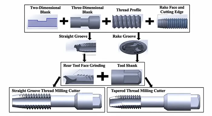
SolidWorks was used to develop three-dimensional models of straight-flute and spiral-point taps. The modeling process included blank creation, MJ thread geometry, thread relief, cutting chamfers, chip flutes, flank grinding, and shank design.
For spiral-point taps, the straight flutes were additionally modified into inclined cutting grooves. The tap thread dimensions followed the requirements of the MJ6 internal thread standard.
Finite Element Model Development and Validation
ABAQUS provides powerful nonlinear solving capabilities suitable for tapping simulations involving large deformation and complex contact conditions. The modeling procedure includes part creation, material assignment, assembly, output configuration, meshing, contact definition, loading, simulation, and postprocessing.
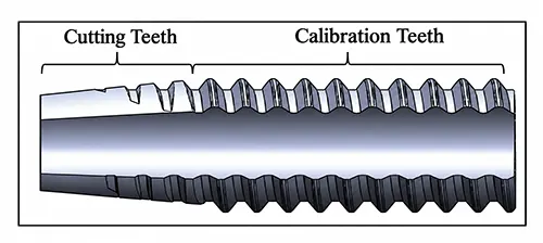
During tapping, the cutting teeth carry most of the mechanical load. Therefore, these regions are the primary focus of the simulation.
Previous research reported approximately 4,320 hours for simulating a complete workpiece using Deform 3D. To improve computational efficiency, this study uses a localized cutting tool model.
An additional calibration tooth was added to each side of the cutting teeth. This arrangement enables the simulation to generate a complete internal thread profile.
The initial workpiece height was set to 1.2P, where P represents the thread pitch.
To maintain thread quality while improving simulation efficiency, different workpiece central angles were investigated at a fixed height. The final model used a 15° central angle and a height of 1.2P.
Simulation results showed a smooth internal thread profile with good surface quality. The selected geometry also helped prevent surface defects.
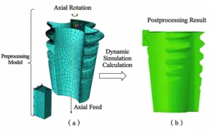
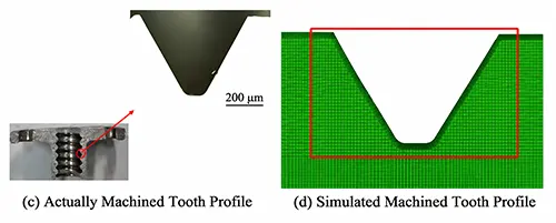
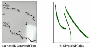
Figure 4 compares experimental tapping results with finite element simulation results. Actual automatic tapping produced long, slender chips that closely matched the simulated chip morphology.
The internal thread metallographic structure was also compared with the simulated thread profile. Simulation results showed a complete thread form without obvious cracks or surface damage.
The thread root exhibited a smooth, rounded transition. Its geometry closely matched the internal thread produced by the automatic tapping machine.
These comparisons confirmed the effectiveness of the finite element model. Both chip morphology and thread profile demonstrated good agreement between simulation and experiment.
Single-Factor Experimental Design for Tapping
Tap geometry and spindle speed strongly influence tapping performance. This study selected maximum tapping torque as the optimization indicator.
The single-factor analysis examined a spiral-point tap with an 8.5° chamfer angle. Other parameters included inclination angle, rake angle, clearance angle, and spindle speed.
The inclination angles were 8°, 9°, and 10°. Rake angles were 9°, 11°, and 13°, while clearance angles were 4°, 5°, and 6°.
Spindle speeds were set to 390, 420, and 450 r/min.
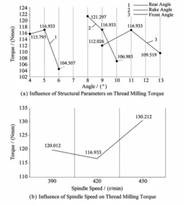
Within the selected experimental range, tapping torque initially increased slowly as the clearance angle increased. It then decreased rapidly at larger clearance angles.
A relatively large clearance angle can therefore improve tapping performance, provided sufficient cutting tool strength remains.
Increasing the cutting edge inclination angle gradually reduced tapping torque. A larger inclination angle increases the effective rake angle and produces a sharper cutting edge.
This geometry facilitates material removal and reduces cutting resistance.
As the rake angle increased, tapping torque initially increased before decreasing. Spindle speed produced a different response.
Torque initially decreased as spindle speed increased, then rose more rapidly at higher speeds. Therefore, moderate spindle speeds are preferable for practical tapping operations.
Orthogonal Experimental Design for Spiral-Point Tapping
Orthogonal Experimental Scheme
Numerous parameters influence tapping torque, and their interactions are complex. Orthogonal experimental design provides reliable parameter combinations while reducing experimental time and cost.
Four major factors were selected: cutting edge inclination angle, rake angle, clearance angle, and spindle speed. Maximum tapping torque served as the primary evaluation indicator.
The factor levels appear in Table 1.
| Level | Inclination Angle (°) | Rake Angle (°) | Clearance Angle (°) | Spindle Speed (r/min) |
|---|---|---|---|---|
| 1 | 8 | 9 | 4 | 390 |
| 2 | 9 | 11 | 5 | 420 |
| 3 | 10 | 13 | 6 | 450 |
Table 1. Factors and Levels for Orthogonal Experimental Design
An L9 orthogonal array was selected based on the experimental factors and levels. Table 2 presents the nine experimental combinations and their corresponding maximum torque and axial force values.
| Test | Inclination Angle (°) | Rake Angle (°) | Clearance Angle (°) | Spindle Speed (r/min) | Maximum Torque (N·mm) | Maximum Axial Force (N) |
|---|---|---|---|---|---|---|
| 1 | 8 | 9 | 4 | 390 | 102.380 | 38.896 |
| 2 | 8 | 11 | 5 | 420 | 121.297 | 45.984 |
| 3 | 8 | 13 | 6 | 450 | 115.092 | 43.792 |
| 4 | 9 | 9 | 5 | 450 | 109.401 | 40.930 |
| 5 | 9 | 11 | 6 | 390 | 125.391 | 56.194 |
| 6 | 9 | 13 | 4 | 420 | 100.467 | 38.080 |
| 7 | 10 | 9 | 6 | 420 | 122.160 | 46.223 |
| 8 | 10 | 11 | 4 | 450 | 119.452 | 44.950 |
| 9 | 10 | 13 | 5 | 390 | 116.606 | 44.522 |
Table 2. Orthogonal Experimental Results for Tapping Torque
Range Analysis
Range analysis was applied to the results in Table 2. This method identifies the relative importance of experimental factors, their optimal levels, and the preferred parameter combination.
The method is also known as the R method.
K1, K2, and K3 represent the sums of experimental results at each factor level. Their corresponding mean values describe the average response at each level.
The range R represents the difference between the maximum and minimum mean values. A larger R indicates a stronger influence on tapping torque.
Table 3 summarizes the range analysis results.
| Parameter | Inclination Angle (A) | Rake Angle (B) | Clearance Angle (C) | Spindle Speed (D) |
|---|---|---|---|---|
| K1 | 338.769 | 333.941 | 322.299 | 344.377 |
| K2 | 335.259 | 366.140 | 347.304 | 343.924 |
| K3 | 358.218 | 332.165 | 362.643 | 343.945 |
| Mean K1 | 112.923 | 111.314 | 107.433 | 114.792 |
| Mean K2 | 111.753 | 122.047 | 115.768 | 114.641 |
| Mean K3 | 119.406 | 110.722 | 120.881 | 114.648 |
| R | 7.653 | 11.325 | 13.448 | 0.151 |
Table 3. Range Analysis of Tapping Parameters
The influence ranking was C > B > A > D. Therefore, clearance angle had the greatest influence, followed by rake angle and cutting edge inclination angle.
Spindle speed showed the smallest influence within the investigated range.
Reducing maximum tapping torque helps improve tool life and internal thread quality. Therefore, the optimal factor levels correspond to the minimum mean torque values.
The optimal combination was C1B3A2D2.
This combination specifies a 4° clearance angle, 13° rake angle, and 9° cutting edge inclination angle. The corresponding spindle speed is 420 r/min.
Among the nine experimental combinations, Test 6 achieved the lowest maximum tapping torque of 100.467 N·mm. Its maximum axial force was 38.080 N.
Conclusion
An ABAQUS finite element model was developed and validated for MJ thread tapping. The study examined how tap geometry and machining parameters influence maximum tapping torque.
Orthogonal experimental design and range analysis identified the relative importance of four parameters. Clearance angle had the greatest influence, followed by rake angle, cutting edge inclination angle, and spindle speed.
The optimal configuration included a 4° clearance angle, 13° rake angle, and 9° cutting edge inclination angle. The recommended spindle speed was 420 r/min.
Optimizing these parameters provides a technical foundation for efficient production of nuts with small-diameter MJ threads. The results also support improvements in tapping stability and internal thread quality.