
In the precision machining of mold cavities today, traditional preparatory processes commonly suffer from issues such as uneven material allowances, significant cumulative errors, poor stability in the precision of the core grinding process, and high scrap rates, making it difficult to meet the efficiency and precision requirements of mass production.
Existing processes largely rely on a step-by-step milling combined with single-head profile grinding, which suffers from drawbacks such as cumbersome procedures, high costs, and inconsistent quality.
The innovation of this study lies in optimizing the milling process through the integrated design of specialized composite cutting tools, while simultaneously adopting a dual-head differential profile grinding process and optimizing parameters across four process steps, thereby balancing machining accuracy and production efficiency.
Optimization of Internal Cavity Milling Processes
Internal cavity milling is a critical preparatory process before grinding; the dimensional consistency and uniformity of the machining allowance in the milled cavity directly determine the machining quality and efficiency of the subsequent grinding process.
This study compared three methods—wire cutting, conventional step-by-step milling, and composite profile milling—and ultimately established an optimized composite indexable milling method. The specific process is as follows.
Test Comparison of Traditional Wire-Cut EDM and Conventional Step-by-Step Milling
The wire-cutting machining approach involves rough-cutting the internal cavity using a wire-cutting machine.
In actual testing, it was found that cutting the internal cavity of a single LR45 slide block took nearly 180 minutes.
During the process, electrode wire wear caused dimensional variations, and the unit processing cost was more than three times that of conventional milling.
Due to its low efficiency and high cost, this approach fails to meet the requirements for mass production and was therefore immediately ruled out.
The conventional step-by-step milling approach involves breaking down the complex cross-section of the internal cavity into multiple simple machining units and completing the machining in four separate passes.
The VDL1000 precision vertical machining center was selected as the machining equipment, with hydraulic vise clamping used for workpiece securing.
This approach requires a total of four specialized cutting tools: a long-fluted end mill, a T-slot milling cutter, a 45° angle milling cutter, and a composite finishing milling cutter.
Multiple tool changes are necessary, resulting in a total machining cycle time of 150 minutes.
Post-machining inspection revealed that cumulative errors resulting from multiple clamping and tool changes led to poor dimensional consistency in the cavity cross-section.
The resulting grinding allowance fluctuated between 0.2 and 0.8 mm, and the uneven allowance not only increased the labor hours required for subsequent grinding but also led to scrap due to insufficient local allowance, failing to meet the production efficiency requirements for mass production.
Design of an Optimized Composite Indexable Form Milling Solution
To address the issues associated with conventional step-by-step milling, this study involves the optimized design of a specialized composite indexable carbide form milling cutter.
The overall structural parameters are designed to meet the requirement of completing the entire machining operation in a single pass, and the cutter’s geometric parameters satisfy the following relationships:
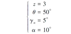
Here, z represents the number of teeth on the milling cutter, θ represents the flute angle, γn represents the normal rake angle, and α represents the clearance angle.
The cutter incorporates seven coated carbide inserts of different shapes, with each insert machining a specific section of the internal cavity.
The cutter body uses 40CrNiMoA alloy structural steel.
Quenching and tempering increase the cutter body’s hardness to 280–300 HB.
The shank uses a BT40 taper, and the taper surface undergoes additional nitriding and hardening treatment to achieve a hardness of 50 to 55 HRC, ensuring the taper’s precision and wear resistance.
Once assembled with set screws, this milling cutter can be stored directly in the machine tool’s disk-type tool magazine.
During machining, a robotic arm automatically loads it into the spindle taper bore, eliminating the need for manual tool loading and adjustment.
The clamping method follows the existing process, utilizing a hydraulic vise on a vertical machining center to maintain consistency among the design, process, and measurement reference surfaces.
The entire internal cavity machining is completed in a single setup, thereby reducing errors caused by reference surface transitions.
Cutting Tests and Analysis of Results for the Optimized Milling Process
The blank selected for this cutting test was the same as that used before optimization.
The blank’s external dimensions were 120 × 51 × 520 mm, with a grinding allowance reserved on the four faces measuring 120 × 51 mm.
The process machined five parts from a single blank. It positioned and clamped the workpiece using reference surfaces A and B and performed up-milling with emulsion coolant.
The process includes two machining steps: rough milling and finish milling.
It completes both steps in a total cycle time of 30 minutes. After machining, the inspection team selected three parts for dimensional inspection.
The results showed that the maximum symmetry deviation of the two side surfaces of the internal cavity was 0.03 mm, and the maximum straightness deviation over the 520 mm length was 0.03 mm.
The dimensional difference between the grooves at both ends was 0.03 mm, and the surface roughness Ra reached 1.6 μm, fully meeting the dimensional requirements for this process.
The optimized milling process controls the grinding allowance variation for all sampled parts within 0.3–0.4 mm and improves allowance uniformity by more than 70%.
Compared with the original process, the optimized solution reduces the number of cutting tools from five to one.
It also shortens the machining cycle time from 150 minutes to 30 minutes, increases machining efficiency by 80%, and lowers tooling costs by 45%.
This cutting test validated the feasibility of the optimized solution.
Summary of Results from the Optimized Milling Process
This milling process optimization addressed the cumulative error issues caused by the multiple operations and tools in the original process.
All internal cavity surface machining is now completed in a single setup and a single machining operation.
The unification of reference points has reduced positioning, clamping, and measurement errors, resulting in a significant improvement in machining accuracy and stability.
Finish milling produces highly consistent cavity dimensions and uniform grinding allowances.
These improvements create favorable conditions for subsequent precision grinding and significantly reduce grinding accuracy issues caused by uneven material allowances.
The integrated tool design reduces tool changeover time and lowers tool procurement and storage costs, making it suitable for mass production (see Figure 1).
After three months of small-batch trial production, the optimized milling process reduced the scrap rate from 4.2% to less than 0.5% and shortened the machining time per part by 80%.
This fully meets the requirements for mass production, validating the stability of this optimization scheme and allowing for the transition to parameter optimization for the subsequent grinding process.
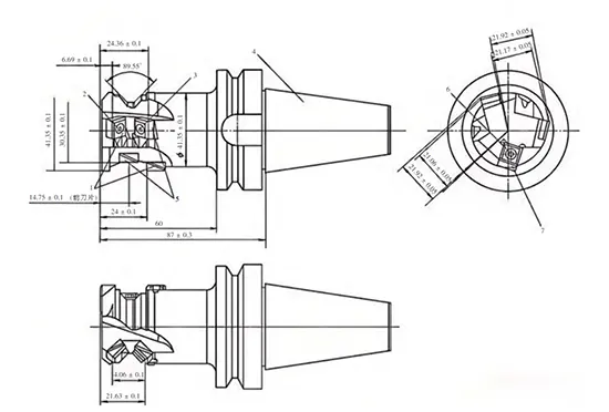
Note: 1. Blade; 2. Screw; 3. Screw; 4. Tool holder; 5. Blade; 6. Screw; 7. Blade
Optimization of Process Parameters for Precision Grinding of Internal Cavities
Carburizing and quenching cause slight deformation in the internal cavities.
Precision grinding corrects this deformation and ensures the dimensional and geometric accuracy of the internal cavity raceways.
This process is critical to determining the final product quality. In this study, addressing the issues associated with conventional grinding, we conducted optimization and experimental validation focusing on both the process scheme and cutting parameters.
Design of a Differential Profiling Grinding Process
Traditional grinding processes use single-head profile grinding wheels and rely on a single diamond roller to dress the grinding wheel on a specialized machine tool.
Due to the effects of quenching distortion, the precision of the inner cavity surface after grinding is low and errors are significant, resulting in a scrap rate as high as 8% and a long machining cycle.
This optimization employs a differential profile grinding process, utilizing the forward-backward phase difference between the two grinding heads of equal height at the left and right ends of the grinding machine to achieve differential feed grinding.
The process uses a precision CNC grinding machine manufactured in Italy together with an electromagnetic chuck for workpiece clamping.
The electromagnetic chuck clamps eight slide blocks simultaneously in a single setup, allowing the grinding machine to fully utilize its processing capacity.
The grinding wheel selected is a macroporous type with a grit size of 80, hardness grade G, and structure number 12.
This type of grinding wheel has good self-sharpening properties, is not prone to clogging, and is suitable for machining high-hardness parts after carburizing and quenching.
The process mounts the grinding wheel on two vertical grinding heads using a dedicated grinding shaft and screws.
The CNC dresser carries a high-precision diamond roller.
Before dressing, the system activates the grinding head dresser and coolant. After dressing, the machine automatically performs dynamic balancing on the grinding wheel to ensure rotational accuracy.
Clamping and positioning follow the previous reference system, using reference surfaces A and B for alignment and correction.
An electromagnetic chuck securely holds surface A in place, ensuring stable clamping without loosening.
Optimization and Experimental Validation of Grinding Process Parameters
To achieve optimal machining accuracy and efficiency, this experiment divided the grinding process into four stages:
rough grinding, semi-finish grinding, finish grinding, and polishing.
The process adjusts the feed rate and cutting depth for each of the four grinding stages while maintaining a constant grinding wheel linear speed of 35 m/s.
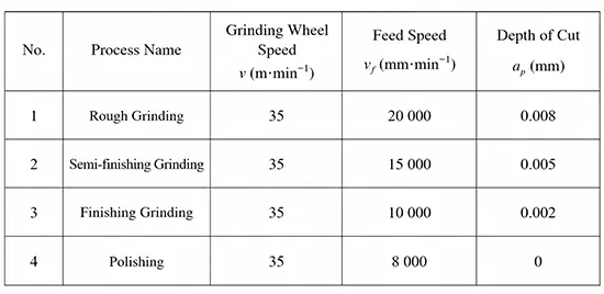
Table 1 summarizes the optimized cutting parameters. The rough grinding stage uses a higher feed rate and a greater cutting depth to rapidly remove most of the remaining material.
The process adopts a feed rate of 20,000 mm/min and a cutting depth of 0.008 mm during the rough grinding stage.
The semi-finishing stage reduces the feed rate and cutting depth to correct machining errors from rough grinding;
The feed rate was set at 15,000 mm/min, and the cutting depth at 0.005 mm. The semi-finishing stage further reduces these parameters to ensure precision, with a feed rate of 10,000 mm/min and a cutting depth of 0.002 mm;
Finally, the process enters the finishing stage, using a cutting depth of 0 mm and a feed rate of 8,000 mm/min to eliminate grinding stresses and reduce surface roughness.
> Production Trial Results
The trial produced 120 finished parts across three batches, and the jointly developed automatic inspection system inspected every part.
The inspection results showed that the contour and positional errors of the internal cavities remained within ±0.003 mm, meeting the precision requirements for finished products.
The optimized process reduced the scrap rate from 8% to below 0.8% and shortened the machining cycle time per part by 40% compared with the original process.
The method of machining eight parts in a single setup fully utilized the production capacity of the CNC equipment.
> Automatic Inspection Performance
The inspection process was also optimized. The jointly developed precision CNC automatic inspection device with a roller slide achieved a repeatability accuracy of 0.00056 mm, straightness measurement accuracy of 0.0011 mm.
It takes only about 10 seconds to inspect a single part, and the system can automatically print inspection reports, fully meeting the inspection requirements for mass production. Inspection efficiency has increased more than 10-fold compared to the previous manual inspection process.
The trial confirmed the feasibility of the optimized grinding parameters and demonstrated their suitability for direct application in mass production.
Conclusion
In summary, the process optimization for mold cavity machining achieved significant results.
The optimized milling process uses a specialized composite indexable form milling cutter to complete all machining operations in a single setup.
This approach reduces the total machining cycle time from 150 minutes to 30 minutes. It also improves machining allowance uniformity by more than 70% and lowers the scrap rate from 4.2% to less than 0.5%.
In the grinding process, the use of differential profile grinding combined with optimized step parameters ultimately controlled part contour errors within ±0.003 mm, reduced the scrap rate from 8% to below 0.8%, and shortened the machining cycle by 40%.
These results fully meet the precision and efficiency requirements for mass production and serve as a reference for machining similar cavities.