
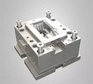
A mold is assembled from numerous components, and the quality of these components directly affects the quality of the mold.
The final quality of the components, in turn, is ensured by the finishing process; therefore, effective control of the finishing process is of critical importance.
In most domestic mold manufacturing enterprises, the methods generally used during the finishing stage include grinding, electrical discharge machining (EDM), and manual machining.
At this stage, it is essential to control numerous technical parameters, including part deformation, internal stresses, geometric tolerances, and dimensional accuracy.
While practical implementation often presents significant challenges, there are still many proven and effective methods worth adopting.
The machining of mold components can be broadly categorized into three types based on their external shapes: plates, irregularly shaped parts, and shafts.
Their common manufacturing process generally follows this sequence: rough machining—heat treatment (quenching, tempering)—finish grinding—electrical discharge machining (EDM)—fitting and machining (surface treatment)—assembly and machining.
Heat Treatment of Parts
The heat treatment process for parts not only ensures that the parts achieve the required hardness but also controls internal stresses to guarantee dimensional stability during machining.
Different materials require different treatment methods.
With the development of the mold industry in recent years, the variety of materials used has increased.
In addition to Cr12, 40Cr, Cr12MoV, and cemented carbide, new powdered alloy steels such as V10 and ASP23 can be selected for punch and die components subjected to high working stresses and severe loading conditions.
These materials possess high thermal stability and favorable microstructures.
Heat Treatment of Cr12MoV Parts
For parts made of Cr12MoV, quenching is performed after rough machining.
After quenching, the workpiece retains significant residual stress, which can easily lead to cracking during finishing or in service.
Therefore, the part should be tempered while still hot to eliminate the quenching stresses.
The quenching temperature should be controlled between 900–1020°C, followed by cooling to 200–220°C before removing the workpiece from the furnace for air cooling.
The workpiece is then rapidly returned to the furnace for tempering at 220°C.
This method, known as the single-stage hardening process, yields high strength and wear resistance, making it particularly effective for molds where wear is the primary failure mode.
For workpieces with numerous corners and complex shapes encountered in production, tempering alone is insufficient to eliminate quenching stresses;
Stress-relief annealing or multiple aging treatments must be performed before finishing to release the stresses fully.
Heat Treatment of Powdered Alloy Steels
For parts made of powdered alloy steels such as V10 and APS23, which can withstand high-temperature tempering, a two-stage hardening process can be used during quenching:
quenching at 1050–1080°C, followed by high-temperature tempering at 490–520°C repeated multiple times.
This yields high impact toughness and stability, making it well-suited for molds where chipping is the primary failure mode.
Although powder alloy steel is relatively expensive, its superior performance is driving a trend toward its widespread adoption.
Grinding of Parts
There are three main types of machine tools used for grinding: surface grinders, internal and external cylindrical grinders, and tool and die grinders.
During finish grinding, grinding deformation and the formation of grinding cracks must be strictly controlled; even the smallest cracks will become apparent during subsequent machining and use.
Therefore, the feed rate for finish grinding must be small—not large—and sufficient coolant must be applied.
Temperature Control and Grinding Wheel Selection
Parts with dimensional tolerances within 0.01 mm should be ground under constant temperature conditions whenever possible.
Calculations show that for a 300-mm-long steel workpiece, a temperature difference of 3°C results in a material change of approximately 10.8 μm (10.8 = 1.2 × 3 × 3, where the deformation per 100 mm is 1.2 μm/°C).
The impact of this factor must be fully considered in all finishing operations.
Selecting the appropriate grinding wheel is crucial for precision grinding. Given the high vanadium and molybdenum content in mold steel, GD single-crystal alumina grinding wheels are particularly suitable.
When machining cemented carbide or materials with high quenched hardness, diamond grinding wheels with organic bonding agents should be prioritized.
Organic-bonded diamond grinding wheels exhibit excellent self-sharpening properties and can achieve a surface roughness of Ra = 0.2 μm on the workpiece.
In recent years, with the application of new materials, CBN grinding wheels—that is, cubic boron nitride grinding wheels—have demonstrated excellent machining results.
In finishing operations on CNC profile grinders, coordinate grinders, and CNC internal and external cylindrical grinders, their performance surpasses that of other types of grinding wheels.
During grinding operations, it is important to dress the grinding wheel promptly to maintain its sharpness.
When the grinding wheel becomes dull, it will skid and squeeze against the workpiece surface, causing surface burn and reduced strength.
Grinding of Plate-Type Parts
Most plate-type parts are machined using surface grinders. During machining, one often encounters long, thin plate parts, which are particularly difficult to machine.
This is because, during machining, the workpiece deforms under the force of the magnetic chuck and presses tightly against the table surface.
When the workpiece is removed, it undergoes elastic recovery. Although the measured thickness remains consistent, the parallelism fails to meet requirements.
A solution is to use the magnetic-shielded grinding method: place a shim of equal height under the workpiece during grinding and secure it tightly with stops on all four sides. Use small feed rates and perform multiple finishing passes.
After one side is machined, the shims can be removed, and the workpiece can be machined directly under magnetic clamping. This improves the grinding results and meets the parallelism requirements.
Grinding of Shaft-Type Parts
Shaft-type parts feature rotating surfaces, and their machining widely employs internal and external cylindrical grinders as well as tool grinders.
During the machining process, the headstock and center act as the generatrix; if runout issues exist, the machined workpiece will exhibit the same problem, affecting part quality.
Therefore, thoroughly inspect the headstock and center before machining.
During internal bore grinding, apply sufficient coolant to the grinding contact area to ensure smooth removal of grinding debris.
When machining thin-walled shaft-type parts, it is best to use a clamping fixture; the clamping force must not be excessive, otherwise “internal triangular” deformation is likely to occur around the circumference of the workpiece.
Electrical Discharge Machining (EDM) Control
Electrical discharge machining (EDM) is indispensable in modern mold manufacturing facilities.
EDM can process various irregularly shaped and high-hardness parts and is divided into two types: wire cutting and spark erosion.
Slow-wire cutting can achieve a machining accuracy of ±0.003 mm and a surface roughness of Ra 0.2 μm.
Before starting machining, inspect the machine tool’s condition and check various factors—such as the deionization level of the water, water temperature, wire verticality, and tension—to ensure optimal machining conditions.
Wire-Cut EDM and Stress Control
Wire-cut EDM removes material from a solid block, disrupting the workpiece’s original stress balance and easily causing stress concentration, particularly at corners.
Therefore, when R < 0.2, especially at sharp corners, submit design improvement recommendations to the design department.
To reduce stress concentration during machining, apply the principle of vector translation:
Before finishing, leave an allowance of approximately 1 mm to pre-machine the rough shape, followed by heat treatment to release machining stresses prior to finishing, thereby ensuring thermal stability.
Wire Path and Machining Strategy
When machining a punch, carefully consider the wire entry point and cutting path.
For the best results, drill a hole and thread the wire through it. For high-precision wire cutting, use four passes to ensure part quality.
When machining tapered dies, to maximize speed and efficiency, rough-machine the straight edges in the first pass, machine the taper in the second pass, and then finish the straight edges.
This eliminates the need for vertical finishing of the X-section, requiring only finishing of the straight edges along the cutting edge—thereby saving both time and cost.
EDM Electrode Selection and Control
EDM processing begins with electrode fabrication. Divide the electrodes into roughing and finishing types.
Finishing electrodes require high dimensional accuracy, so machine them with CNC machines whenever possible. For electrode material selection, use pure copper electrodes primarily for machining general steel parts.
Cu-W alloy electrodes offer superior overall performance; in particular, their material consumption during machining is significantly lower than that of pure copper.
With an adequate supply of flushing fluid, they perform well when machining difficult-to-machine materials and finishing parts with complex cross-sectional shapes.
When fabricating electrodes, it is necessary to calculate the electrode clearance and the number of electrodes required.
For large-area machining or applications involving heavy electrodes, clamp the workpiece and electrodes securely. Ensure sufficient rigidity to prevent loosening during machining.
During deep-step machining, monitor electrode wear at different points. Also, ensure proper coolant drainage to prevent arc discharges.
Surface Treatment and Assembly
Machining marks and grinding marks left on part surfaces during machining are areas of stress concentration and sources of crack propagation.
Therefore, after machining is complete, the parts must undergo surface strengthening through manual grinding to eliminate potential machining-related hazards.
Edges, sharp corners, and hole openings on the workpiece should be chamfered and rounded.
Generally, EDM-machined surfaces develop a hardened layer approximately 6–10 μm thick, which appears grayish-white.
This hardened layer is brittle and contains residual stress; therefore, thoroughly remove it before use by polishing and grinding the surface.
During grinding and EDM processes, the workpiece becomes slightly magnetized and exhibits a weak magnetic field, making it highly prone to attracting small particles.
Therefore, demagnetize the workpiece before assembly and clean its surface with ethyl acetate.
During assembly, first review the assembly drawing to gather all necessary parts.
Then, establish the assembly sequence for each component and list all precautions to observe before proceeding with mold assembly.
Assembly generally begins with installing the guide pins and bushings, followed by the mold base and the punch and die.
Next, perform assembly adjustments to clearances throughout the mold, paying particular attention to the clearance between the punch and die. Upon completion of assembly, conduct a mold inspection and prepare a comprehensive status report.
Trace the finishing operations back to rough machining. Continue the investigation step by step until the root cause becomes clear.
Practice has proven that effective control of the finishing process can significantly reduce dimensional deviations and scrap rates, while effectively improving the first-pass success rate and service life of the mold.
Conclusion
The finishing process is a critical stage in mold manufacturing because it directly affects dimensional accuracy, surface quality, assembly performance, and service life.
Effective control requires a systematic approach to heat treatment, grinding, EDM, surface treatment, and final assembly.
Key factors such as residual stress, thermal deformation, grinding parameters, EDM conditions, machining marks, and assembly clearances require careful control throughout the process.
Selecting appropriate materials, machining methods, grinding wheels, fixtures, and EDM parameters can further improve processing stability and precision.
At the same time, stress relief, proper cooling, surface strengthening, demagnetization, cleaning, and thorough inspection are essential for preventing defects and ensuring reliable mold performance.
Ultimately, finishing quality depends not on a single operation but on coordinated control of the entire manufacturing sequence.
By identifying potential problems and tracing defects backward from final assembly to earlier processes, manufacturers can reduce dimensional deviations and scrap, improve first-pass yield, and extend mold service life.