
The nozzle housing is a critical component of the combustion chamber in civil aviation APUs, primarily used in the Airbus A320 and A321 series aircraft; its machining quality directly determines the engine’s injection performance and flight safety.
Complex structures and high precision requirements generally characterize nozzle housings, and the surface condition of the parts is a key factor affecting their service life and reliability.
Annual demand for these parts stands at 6,000 sets; however, machining GH4169 high-temperature alloy presents challenges such as high work-hardening, high cutting forces, poor thermal conductivity, high cutting temperatures, and tool wear and adhesion.
The original process had numerous shortcomings, resulting in a low yield rate, poor production efficiency, and production capacity that could not meet demand.
Therefore, optimizing the milling process to address issues of precision, efficiency, and surface quality is of great practical significance for ensuring order delivery and improving manufacturing standards.
This study addresses three core pain points—low machining yield, poor production quality, and susceptibility to surface damage—by proposing a comprehensive optimization plan.
Through trial machining to verify the results, the plan achieves dual improvements in both yield and efficiency.
Product Requirements
The nozzle housing is made of GH4169 nickel-based high-temperature alloy, a material that offers high strength, high-temperature resistance, and creep resistance.
It is a commonly used material for core components in aircraft engines, but it has extremely poor machinability.
During machining, the material is highly prone to plastic deformation and work hardening, leading to phenomena such as tool sticking and built-up edge, which cause rapid tool wear and make it difficult to consistently ensure dimensional accuracy of the parts.
At the same time, the part has a complex structure, featuring a series of irregularly shaped angled holes, and the internal cavity space is narrow and compact, making tool interference and collisions highly likely during milling.
Furthermore, the part has stringent precision requirements, with key dimensional tolerances required to be controlled within 0.02 mm.
Among these, the machining accuracy of the 6.64 mm hole, the Φ8.51 mm hole, and the R3.7 mm fillet directly determines the fuel injection performance of the nozzle housing.
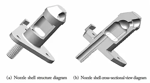
The structural diagram of the nozzle housing is shown in Figure 1(a), and the schematic cross-sectional view of the nozzle housing is shown in Figure 1(b).
Analysis of the Prototype Manufacturing Process
Taking into account the machinability of GH4169 superalloy and the structural characteristics of the part, the machining plan for the nozzle housing prototype is as follows:
(1) CNC turning (rough machining of the blank) → (2) Milling (machining of process grooves) → (3) CNC turning (machining the reverse-side thread) → (4) CNC milling (machining the outer contour and round holes) → (5) manual machining → (6) CNC milling (machining rectangular slots) → (7) Fitter → (8) CNC Milling (machining angled holes) → (9) Fitter → (10) CNC Milling (machining the curved surfaces of the spherical groove) → (11) Fitter → (12) Final inspection.
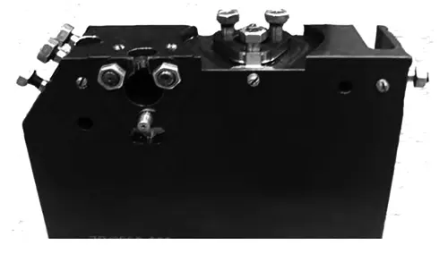
To reduce transfer time during the nozzle housing manufacturing process, the fixtures for the four CNC milling operations were designed as a single set, with four separate setups to complete all milling operations on the product. The prototype milling fixture is shown in Figure 2.
Since each CNC milling operation produces a large amount of burrs, which affect clamping and positioning in subsequent operations, three deburring operations were interspersed among the four CNC milling operations.
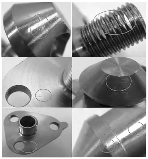
After removing the milling burrs, the parts were re-clamped for further machining. Repeated clamping caused numerous indentations, scratches, and tool marks on the part surfaces.
A total of 60 parts were machined during the pilot production; of these, 41 were acceptable and 19 were unacceptable, resulting in an overall acceptance rate of only 68.33%.
The 19 unacceptable parts had a total of 27 defects, the distribution of which is shown in Table 1.
Among these, the indentations and scratches are shown in Figure 3.
| Table 1. Defect Distribution | Indentation / Scratch | Tool Contact Mark | Countersunk Hole Coaxiality | Others |
|---|---|---|---|---|
| Defect Type | Indentation / Scratch | Tool Contact Mark | Countersunk Hole Coaxiality | Others |
| Quantity | 13 | 7 | 6 | 1 |
| Percentage / % | 48.15 | 25.92 | 22.22 | 3.71 |
Table 1 Distribution of defects
Optimization of Part Machining Processes
Based on the results of the initial production of 60 parts, the product yield rate was only 68.33% when manufactured using this process.
The CNC milling process for this part urgently needs improvement and optimization; the areas for optimization are analyzed as follows.
(1) Difficulty in Ensuring Dimensional Accuracy:
- The tolerances for key dimensions are stringent;
- GH4169 is prone to tool sticking and the formation of built-up edges;
- repeated clamping leads to inconsistent positioning references;
- and machining the same location with multiple tools can easily result in tool change marks.
(2) Low production efficiency:
- Tools wear out quickly, and tool changes and first-piece inspections are time-consuming;
- the process flow is cumbersome, with frequent clamping;
- unreasonable tool selection, cutting parameters, and programs result in a single-part machining time as long as 80 minutes.
(3) Severe and Frequent Surface Damage: The hard material of the washers, the tendency for wrenches to slip, and repeated
clamping or collisions during transport can all lead to indentations and scratches on the part’s surface.
Optimization of the Machining Process
To address the issues of a cumbersome milling process and excessive setups, we leveraged the capabilities of a four-axis machining center to streamline the process from four setups and seven operations to two setups and a single operation, achieving “single setup with integrated multi-operation machining” and reducing handling and positioning errors.
Optimized Process Sequence:
(1) CNC Lathe (rough machining of blank) → (2) Milling (machining of process grooves) → (3) CNC Lathe (machining the reverse-side thread) → (4) CNC milling (clamped in a special fixture, milling all features) → (5) Fitting (deburring, finishing) → (6) Final inspection.
The optimized process has significantly shortened the cycle time and improved equipment utilization.
Custom Fixture Design
Conventional fixtures are only compatible with three-axis machining centers, requiring four clamping and positioning operations during machining.
This not only makes the process cumbersome and reduces production efficiency but also leads to cumulative positioning errors due to repeated clamping, severely limiting part machining accuracy.
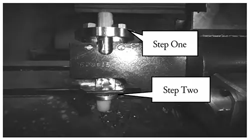
This newly designed specialized four-axis fixture innovatively implements a “two-clamping, simultaneous dual-part machining” mode, enabling the completion of all four milling operations from the original process in a single setup.
This not only completely resolves industry pain points such as positioning errors from multiple setups, lengthy process transitions, and excessive waiting times, but also simplifies manual operations, reduces operational complexity, and significantly improves the geometric and positional machining accuracy of parts.
Specifically, the first machining step completes the milling of the part’s outer contour and angled hole structures, while the second step focuses on the precision machining of spherical groove features.
A real-life photo of the optimized fixture in use is shown in Figure 4.
Optimization of Protective Measures
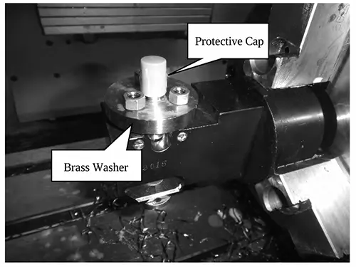
To effectively prevent and control surface damage and defects in parts during clamping, assembly, disassembly, transportation, and storage, five standardized protective measures have been established based on actual production conditions.
(1) During the assembly and clamping stages, use H62 brass washers.
This material has a moderate hardness that can cushion the clamping force and prevent surface indentations on the workpiece caused by rigid compression;
(2) Reuse the original manufacturer’s specialized plastic protective caps to fully cover threaded structures, preventing accidental knocks or scratches to threaded areas during part handling;
(3) Provide a dedicated 12-point internal hex wrench to improve the engagement and fit between the tool and the workpiece, thereby eliminating impact damage caused by the wrench slipping;
(4) Standardize on-site work procedures; thoroughly clean the workstation of metal shavings and hard debris before clamping to prevent surface indentations caused by foreign objects being pinched;
(5) Use dedicated foam trays uniformly for both part storage and process transfer to ensure compartmentalized placement, thereby preventing surface damage caused by friction and collisions between parts at the source.
A photo of the protective measures in use is shown in Figure 5.
Customized Special-Purpose Cutting Tools
In the pilot production process, the inclined holes on the parts are machined using a step-by-step, combined approach involving multiple cutting tools.
Due to differences in tool materials and cutting conditions, the wear rates of the various tools varied significantly.
This resulted in cumbersome and complex tool parameter compensation and on-site debugging processes.
Furthermore, machining in areas involving multiple tools was highly prone to producing noticeable tool change marks, which severely affected the surface finish and dimensional accuracy of the bore walls.
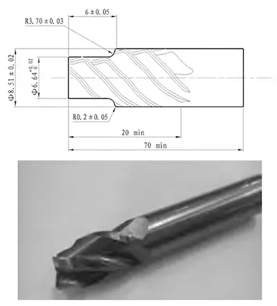
After process optimization, a specialized forming tool was custom-designed for this angled hole configuration, which can complete the integrated forming of the Φ6.64 mm hole, the Φ8.51 mm hole, the R3.7 mm arc, and the critical dimension of 6±0.05 mm in a single operation.
This solution effectively ensures dimensional consistency of the structure, reduces the frequency of tool changes and setup procedures, and, while improving machining efficiency, significantly enhances the surface finish quality of the bore.
The design drawing and physical model of the forming tool are shown in Figure 6.
Optimization of Cutting Parameters
During the initial prototyping process, the cutting speeds for milling the nozzle housing were mostly concentrated in the range of 20–40 m/min.
This speed range falls precisely within the range where alloy-built-up edges are most likely to form.
During cutting, built-up edges are highly prone to forming at the cutting edge, which not only compromises the surface finish of the part but also accelerates tool wear and shortens tool life.
Therefore, the speed was adjusted to approximately 18 m/min, precisely avoiding the range where built-up edges form.
At the same time, the spindle speed and feed rate for the cutting tools in each process were optimized, effectively suppressing abnormal tool wear and significantly extending tool life.
A comparison of the key tool parameters before and after optimization is shown in Table 2.
| Tool | Before Optimization | After Optimization | ||
|---|---|---|---|---|
| Spindle Speed(r·min⁻¹) | Feed Rate(mm·min⁻¹) | Spindle Speed(r·min⁻¹) | Feed Rate(mm·min⁻¹) | |
| Φ10 End Mill | 900 | 80 | 600 | 100 |
| Φ8 End Mill | 1,200 | 80 | 750 | 90 |
| Φ6 End Mill | 1,500 | 80 | 950 | 80 |
| Φ3 End Mill | 2,300 | 70 | 1,900 | 80 |
| Φ6.5 Drill Bit | 1,200 | 70 | 800 | 80 |
| Form Tool | 800 | 15 | 500 | 20 |
Table 2. Cutting Parameters of Main Machining Tools Before and After Optimization
Comparison of Improvement Results
A total of 2,954 parts were produced across 10 batches using the optimized process. The results, compared to the original process, are as follows.
(1) Significant increase in pass rate:
After optimization, the average pass rate reached 99.05%.
Among these, two batches achieved a 100% pass rate.
(2) Efficiency increased substantially:
Processing time per part was reduced from 80 minutes to 30 minutes, representing a 167% increase in efficiency.
Process turnaround and tool change times were reduced, meeting the production demand of 6,000 sets per year.
(3) Improved Surface Quality:
Issues such as indentations and scratches have been completely resolved, eliminating the need for extensive rework by machinists and saving on labor costs.
(4) Cost Reduction:
Tool life has been extended, rework has been reduced, and equipment utilization has improved, resulting in a significant decrease in overall costs.
The optimized process is stable and reliable, making it suitable for mass production.
Conclusion
To address the bottlenecks in the milling process of nozzle housings, this study addressed the issue from five dimensions: process flow restructuring, fixture design, custom tooling, and cutting parameter optimization.
It optimized the overall machining process layout, designed a dedicated four-axis positioning fixture, customized form-fitting cutting tools, optimized safety measures, and selected optimal milling parameters based on the cutting characteristics of the GH4169 high-temperature alloy.
Following validation through batch machining of 10 batches totaling 2,954 parts, the milling pass rate of the optimized parts increased to 99.05%, production efficiency improved by 167%, and the issue of surface damage to the workpieces was completely resolved, fully meeting the requirements for mass production.
The process approach and technical solutions developed in this study can be applied to the milling of similar, complex-structured, high-temperature alloy parts. They are highly practical for engineering and possess significant value for industry-wide promotion and application.