
Measuring instruments for roundness and cylindricity are used to measure roundness and cylindricity errors.
Based on the method of forming the reference rotation axis, they can be classified into workbench rotation type and sensor rotation type.
In the workbench rotation type, the workpiece rotates with the workbench while the sensor remains fixed; in the sensor rotation type, the sensor rotates while the workpiece remains fixed.
High precision requirements make roundness and cylindricity measurements sensitive to minor errors.
This article analyzes factors affecting measurements using the Talyrond 585 PRO roundness instrument.
Principle
Roundness and cylindricity instruments use the radius measurement method, with a high-precision rotating spindle as the measurement reference.
Measuring the part’s surface contour at one or more cross-sections at different rotation angles determines roundness and cylindricity errors.
Roundness and cylindricity instruments measure contour deviations via a precision spindle to quantify roundness or cylindricity.
Common Influencing Factors and Solutions
Measurement inaccuracies caused by external vibrations
Cylindricity and roundness instruments need high precision, and environmental factors—especially vibration—can distort measurements.
To ensure accurate, reliable data, place the instrument on a stable, independently supported workbench and measure under proper operating conditions.
Measurement inaccuracies caused by unstable air pressure
High-precision roundness and cylindricity instruments use air-bearing spindles to drive mostly suspended rotary workbenches.
Air-bearing suspension lifts the spindle and workbench with gas, reducing friction and vibration for more accurate measurements.
Gas supply pressure is critical: prolonged use may cause floating and pressure imbalance.
Too little pressure prevents full suspension, causing contact, friction, and abnormal measurement ripples.
conversely, instability of the spindle and rotating workbench may cause instrument vibration during measurement, affecting the measurement results.
Therefore, during measurement, it is essential to strictly follow the standard air pressure specified on the instrument’s pressure regulator.
Measurement inaccuracies caused by leveling and centering
Roundness and cylindricity instruments use a high-precision rotating spindle as the measurement reference.
During measurement, mount the workpiece concentrically with the spindle so the axis system can move precisely with the air-floating table.
Measurement accuracy depends on the workpiece being coaxial with the spindle, which requires precise leveling and centering beforehand.
To ensure coaxiality with the spindle, place the workpiece on the workbench and make coarse and fine adjustments before measurement.
Manual coarse adjustment: place the sensor, rotate once, check displacement, and tap if needed to keep it under 300 μm.
The instrument automatically performs fine adjustment and repeats the process until it meets the requirements.
Figure 1 shows the instrument’s automatic leveling and centering interface.

Inaccurate measurement results caused by uncalibrated sensors and probes
The calibration of sensors and probes essentially involves self-correction of sensor linearity.
A sensor’s output should linearly correspond to the measured quantity; this correspondence defines its linearity.
The smaller the linearity error, the higher the sensor linearity, and the more accurate the measurement results.
For high-precision objects, you must calibrate the sensors and probes before measurement if the direct results lack accuracy or reliability.
Most roundness and cylindricity gauges include one or more calibration blocks with reference values for each parameter.
Before use, add reference values to the instrument’s calibration database and select the appropriate standard block.
After calibration with the standard block, the instrument automatically corrects linearity via software to ensure measurement accuracy.
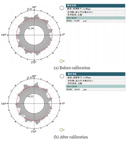
Conduct a roundness measurement test on the same cross-section of the standard cylinder.
Set the reference value for roundness to 0.402 μm. Figure 2 shows the measurement results before and after calibrating the instrument.
As shown by the test, the measurement results after calibration are closer to the reference value.
Inaccurate measurement results caused by unreasonable filter settings
Filtering involves removing specific frequency bands from a signal, which is an important measure to suppress and prevent interference.
Additionally, the selection of reasonable filter bands can significantly impact measurement results.
Different industries have their own filter band requirements, such as the mechanical processing industry, which typically uses (1–50) upr.
To meet customer needs, roundness and cylindricity instruments use frequency bands of 1–15, 1–50, and 1–1500 upr.
Selecting a larger band retains more information in the measurement results and increases the accuracy.
Conversely, selecting a smaller band retains less information in the measurement results and decreases the accuracy.
In practice, larger bands aren’t always better; for rough cylinders, they may let surface roughness skew measurement accuracy.
Assess the part’s surface quality, machining accuracy, and drawing requirements to minimize interference and ensure accurate, reliable measurements.
For roundness tests on the same cylinder cross-section, filter bands of (1–50) upr and (1–150) upr were used; results are in Figure 3.

As shown in Figure 3, an appropriate filter band can mitigate the impact of surface roughness on the accuracy of measurement results.
Conclusion
In summary, environmental, equipment, or setup issues can reduce roundness and cylindricity measurement stability.
Operators should measure in a proper environment with stable air, leveled workpieces, calibrated instruments, and suitable filters.
This will enhance the accuracy and reliability of the measurement results.