Plastic products often encounter cracking during manufacturing and use.
This problem not only affects the product’s appearance but may also compromise its functionality and safety.
Plastic part cracking occurs as demolding cracks during mold removal or machining, and application cracks after storage or in use.
Mold design, molding process, material choice, and environmental stress cause plastic part cracking.
In mold design, improper gates, shallow draft angles, and poor ejection setups cause stress concentration, leading to cracks.
High injection pressure, long hold, or low mold temperature can induce residual stress and cracking.
Material issues like high recycled content, moisture, or poor processing can cause cracking.
Environmental stress cracking happens when stressed products contact reactive media, causing brittle fractures.
Addressing plastic part cracking requires a systematic solution.
Optimize gate design, increase draft angles, and configure ejection mechanisms to reduce stress in mold design.
Second, in molding processes, adjust parameters like injection pressure, holding time, and mold temperature to minimize residual stress.
Select materials suited to the process and minimize metal inserts to ensure plastic quality.
Finally, for already cracked products, post-processing measures like annealing can eliminate internal stresses and reduce crack formation.
To resolve plastic part cracking, comprehensively address multiple factors and apply measures to reduce stress and improve quality.
This analysis of two-year-old panels identifies cracking causes and proposes solutions for other plastic components.
Problem Description
A batch of panel products that have been on the market for two years exhibited varying degrees of surface cracking.
The panel uses a PC/ABS composite with a 10.4-inch display, F-keys, right-side operation area, four top and bottom mounting holes, and eight M4×20 screws.
Figure 1 shows cracks mainly around the four corner mounting holes, some leading to complete breakage.
Market research shows similar panels from other brands crack in the same locations after prolonged use.
This widespread panel cracking issue impedes the normal operation of machine tools and poses safety hazards to personnel.
Cause Analysis
We must analyze both the structural design and the fastening method to identify the root causes of CNC panel failures.
Engineers must monitor areas of concentrated loads, as they often determine reliability.
Among the potential weak points, the mounting holes—where the panel interfaces with screws and the machine body—are especially prone to stress concentration and damage.
The following section focuses on the mounting hole issues observed in failed samples.
Mounting Hole Issues
Figure 2 shows the CNC panel mounting method, with engineers securing it using eight M4×20 screws.
Damaged samples (Figure 1) show failure zones at the eight screws’ critical load-bearing areas.
Cracking around mounting holes requires assessing screw capacity, hole stress, and optimizing sizes.
Stress-bearing and load-bearing areas are key parameters for evaluating screw performance.
Stress-bearing cross-sectional area is the effective area under maximum tensile stress before failure.
Load-bearing area and its ratio to the screw’s stress cross-section determine connection stability and safety.
It shows the support-to-thread load-bearing ratio, directly affecting load distribution and durability.
When selecting screws, consider stress area, load-bearing area, and their ratio.
Table 1 shows stress-bearing and load-bearing areas and their ratios for common screw models.

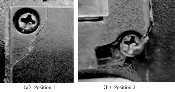
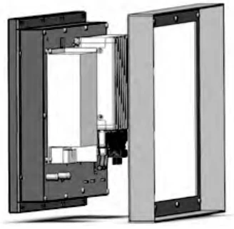
Table 1 shows that increasing screw diameter lowers the bearing-to-stress area ratio.
CNC panels use M4×20 screws, whose low area ratio lowers mechanical performance.
CNC panels must withstand stresses and vibrations, needing screws with adequate load capacity.
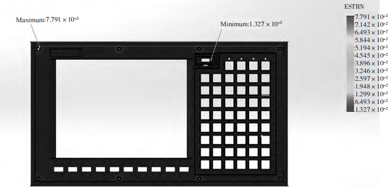
Finite element software simulated stress in CNC panel screw holes using ABS/PC material properties.
We installed M4×20 screws on the simulated fixture and applied 2 N·m torque.
Engineers added fixtures to the panel’s YOZ surface to simulate real conditions and limit degrees of freedom.
Figure 3 shows simulated strain, with maximum 7.791×10⁻² exceeding PC/ABS yield (~5×10⁻²) and necking (~7×10⁻²).
We simulated other screws to assess their effect on panel stress-strain using the same material (Table 2).
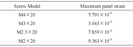
Tables 1 and 2 show the M4×20 screw’s large bearing area but low area-to-stress ratio, causing high strain.
The M2×20 screw’s high bearing-to-stress ratio causes maximum strain and deformation.
The M3×20 screw’s moderate area ratio and low strain yield minimal deformation and optimal performance.
Panel Material
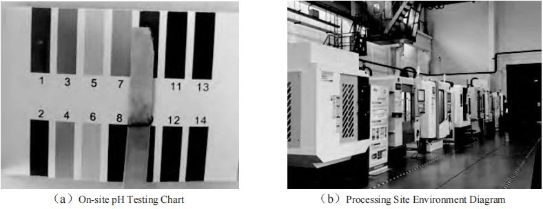
Field analysis shows the machine tool workshop environment is alkaline with oil residue (Figure 4).
The CNC panel uses PC/ABS composite, which combines PC and ABS strengths but inherits their defects.
The alkaline, oily environment weakens PC/ABS composites, reducing component strength and durability.
Corrosion affects screw surfaces and threads, and the panel coating peels and corrodes.
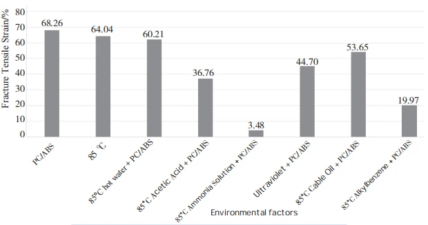
Figure 5 shows PC/ABS fracture tensile strain under different environments.
Ammonia-based alkaline immersion reduces PC/ABS fracture tensile strain to 3.48% (Figure 5).
This occurs because the alkaline environment chemically degrades the material.
PC ester groups become unstable under alkaline conditions and hydrolyze readily with water.
This degrades material properties, causing brittleness and increased susceptibility to cracking.
Cable oil and low-viscosity alkylbenzene immersion reduced fracture elongation to 53.65% and 19.97%.
This shows that oily substances permeate PC/ABS, not reacting chemically but making it brittle.
In a brittle state, the panel’s resistance to impact loads decreases, making it prone to cracking.
Environmental factors, such as pH and oils, are key contributors to panel cracking.
To reduce panel cracking, use materials with better corrosion and oil resistance.
Panel material choice strongly affects CNC panel performance and durability.
Common panel materials on the market include stainless steel, aluminum alloy, and glass.
Each has unique properties. Simulations analyzed different materials to assess stress-induced deformation.
Simulations used consistent panel structures and stress conditions, with results in Table 3.
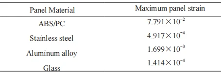
Table 3 shows ABS/PC panels have good formability but high strain and weaker strength and corrosion resistance.
Stainless steel, aluminum, and glass panels show low strains, with glass lowest, indicating superior stability and durability.
Glass is durable but fragile and heavy, making it unsuitable for mobile or high-vibration CNC panels.
Market research shows stainless steel costs 50% more than aluminum and is harder to process.
Evaluation of cost, processing, quality, and chemical stability shows aluminum alloy has distinct advantages.
Aluminum alloy outperforms ABS/PC, offering lower cost, easier processing, and higher quality than steel and glass.
Aluminum alloy’s low cost, light weight, and easy processing make it ideal for CNC panels.
Physical Validation
To enhance the panel’s mechanical properties and prevent cracking, M3×20 screws were selected with aluminum alloy as the panel material.
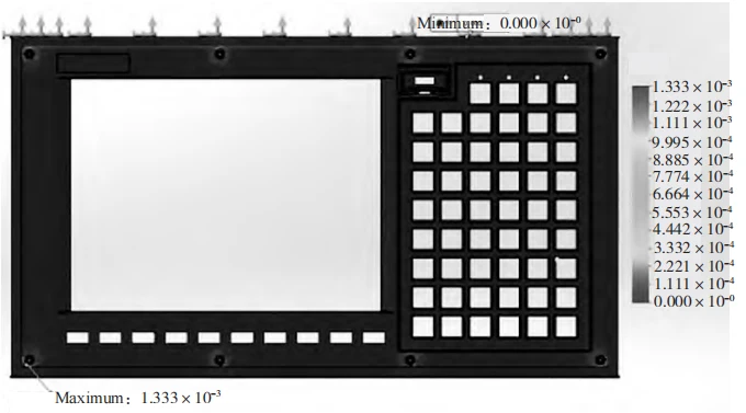
Simulation of the optimized aluminum alloy panel shows post-optimization strain decreased to 1.333×10⁻³ (Figure 6).
Table 4 shows the optimized design raised the bearing-to-stress area ratio by 55% and cut maximum panel strain by 98.3%.
The theoretical results validate the feasibility and effectiveness of the optimization scheme.
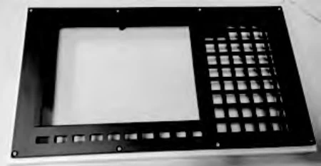
We built aluminum panels and fixtures to test the improved design under real conditions (Figure 7).
Torque Verification
We mounted ABS/PC M4×20 and aluminum M3×20 panels on the fixture and tightened the screws with varying torques to test crack formation; results are in Table 5.
The ABS/PC M4×20 panel cracked at 1.3 N•m, while the aluminum M3×20 panel remained intact at 1.5 N•m.
Tests show the M3×20 aluminum panel stays stable under higher torque than the M4×20 ABS/PC panel, confirming its effectiveness.


Stability Verification
To verify the stability of the panel in actual operating conditions, the aluminum alloy panel was secured to the test fixture with a torque of 1.5 N•m.
We immersed the panel in a 0.8:10 rust-proof solution, then heat-treated it at 80°C for 2 hours.
After baking, the panel was allowed to cool naturally. Preliminary evaluation of its appearance and performance was conducted after 24 hours.
We dried, baked, and naturally cooled the sample for 24 hours, finding no deformation, discoloration, or cracking.
Conclusion
Study of two-year CNC panels optimized screws (M4×20→M3×20) and material (PC/ABS→aluminum), raising load ratio 55% and strength.
This optimized design ensures a secure connection between screws and panels while minimizing stress impact on the panel during assembly.
