
As weak points in the track structure, welded rail joints directly impact operational safety, ride stability, and passenger comfort, as well as track maintenance costs and service life.
To achieve “continuously welded track” and eliminate the impact forces caused by rail gaps, long rails must be joined into a continuous whole through welding processes at specialized rail welding facilities.
These facilities serve as the primary hub and a critical link in the production of high-quality long rails, where the quality of the welded joints is a prerequisite for ensuring superior track smoothness.
Currently, rail welding facilities primarily use flash butt welding, which produces high-strength, reliable joints.
However, this process creates protruding, irregular “weld beads” at the rail joints, disrupting the rails’ original profile and smoothness.
If not meticulously treated, these weld beads can cause severe wheel-rail impact, generate noise, increase dynamic additional loads on the track, accelerate damage to rolling stock and track components, and may even lead to safety incidents such as rail breakage.
Therefore, precise, efficient, and high-quality shaping of weld beads to restore them to the same geometric profile as the rail base material is a key control point for achieving high ride comfort on seamless tracks.
In-depth and systematic research into this process and the exploration of optimized techniques hold significant theoretical and engineering value.
Weld bead finishing technology at rail welding bases has evolved through stages ranging from manual grinding and CNC milling to intelligent processing.
In the early stages, the process relied on manual grinding with handheld grinders, which was labor-intensive, resulted in significant quality fluctuations, and was prone to defects such as over-grinding or under-grinding.
Subsequently, CNC-based full-section rail weld milling machining centers (rough milling machines) were introduced, achieving a precision of up to 0.1 mm; however, manual grinding was still required for areas with weld misalignment.
In recent years, researchers have integrated CNC, robotics, and machine vision technologies to propose an intelligent processing model combining “rough milling machines and robotic arm grinding.”
Based on this model, this paper presents a rail weld bead shaping method that achieves precise, segmented grinding of rail weld beads through the integration of machine vision, flexible force/position hybrid control, and adaptive algorithms.
“Rough Milling Machine + Robotic Arm” Collaborative Operation System
Rough Milling Machine
Based on the technical concept of “milling instead of grinding,” the rough milling machine employs “precision measurement and numerically controlled machining” to replace traditional grinding wheel operations, thereby achieving full-contour shaping of the weld beads on long rails.
However, to realize this precision machining concept of “milling instead of grinding,” it is first necessary to address a core challenge arising from the rail welding process:
deviations inherent in the rolling of the rails themselves. When two rails are welded together, differences in end geometry—such as twist, straightness, rail height, and rail head width—result in a certain degree of misalignment in each weld, with the extent of misalignment varying by location.
If only fixed contour milling cutters are used for machining, issues of insufficient precision are inevitable.
Therefore, multiple sets of custom-made milling cutters are selected in combination with PMC control programs and multi-axis interpolation technology to achieve smooth machining of the rail weld beads.
Based on the above analysis, it is clear that the rough milling machine must convert the preset program into actual smooth machining through precise positioning and measurement.
Through precise and reliable positioning and fixture clamping, the rough milling machine ensures the stable and reliable positioning and machining status of the rail.
It then obtains accurate position data through precision measurements using a micrometer-level probe; the system automatically evaluates the measured data and generates the most suitable machining program.
The implementation of the aforementioned precision measurement and adaptive machining functions relies on a highly integrated and reliable hardware system, the core components of which are as follows:
The rough milling machine consists of a bed movement mechanism, a foundation, a left fixture, a right fixture, a front column, a rear column, a front cross slide, a rear cross slide, a left tool magazine, a right tool magazine, a rail measurement system, a hydraulic system, a tooling system, inspection fixtures, a lubrication system, and an electrical control system.
Robotic Arm
A rough milling machine is a highly specialized, extremely rigid “rigid automation” system.
When machining curved surfaces such as the lower jaw of the rail head and the upper jaw of the rail base, certain high points may remain that cannot be removed, thereby affecting subsequent non-destructive testing results and requiring manual grinding.
To address this challenge, we propose using an industrial six-axis robot (also known as a “robotic arm”) to replace manual grinding, while configuring a flexible force-controlled flange equipped with an electric spindle to ensure a constant grinding force.
Robotic arm grinding is a highly versatile and flexible “flexible automation” solution.
The core of this technology lies in using machine vision for positioning, adaptive grinding, and precision control to remove the 0.5 mm weld bead remaining after rail milling, ensuring a smooth transition between the weld bead and the base material to meet the non-destructive testing requirements of TB/T 1632.1—2014, “Rail Welding—Part 1: General Technical Conditions.”
In the specific operational process, when the weld bead on the conveyor line reaches the grinding zone, the rail is secured and clamped by a hydraulic fixture to ensure its stability during robotic grinding.
The vision inspection system within the equipment automatically identifies the position and height of the rail’s weld bead. Combined with preset programs, the system automatically calculates the grinding area, depth, and path to achieve precise grinding, thereby preventing over-grinding or under-grinding.
As shown in Figure 1, the robotic arm system primarily consists of a robotic arm, a base, a clamping station, grinding tools, a vision inspection mechanism, a video surveillance system, a tool changer, an electrical control system, a hydraulic and pneumatic control system, an external protective enclosure, and a dust collection system.
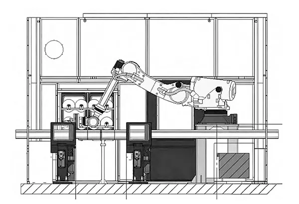
Innovative “Rough Milling Machine + Robotic Arm” Collaborative Operation Model
Combining the operational advantages of rough milling machines and robotic arms, this study employs a two-stage collaborative operation model—“CNC rough milling for pre-shaping + robotic flexible finishing”—to mill welds. The CNC rough milling machine uses a customized set of milling cutters to efficiently remove the main body of the weld bead, strictly controlling the residual weld bead within the range of 0–0.3 mm. This ensures thorough removal of the weld bead while preventing excessive milling depth that could damage the rail base material;
A robotic arm equipped with a 3D line laser scanner performs contour scanning to acquire data such as weld bead height and base material step height. Based on the scan results, the system employs constant force control and trajectory compensation to perform flexible grinding of the rail head, rail web, triangular areas at the rail base, and transition fillets, thereby achieving a smooth transition between the weld and the base material.
Adaptive grinding based on force/position hybrid control is the core technology enabling the robotic arm to achieve high-quality, precise grinding.
Under this control strategy, a force/position controller is connected to the robotic arm’s end effector, and the system switches control modes in real time based on the contact status between the grinding tool and the rail surface.
When the robotic arm is not in contact with the rail (including the approach phase and the retraction phase after grinding), the system employs a pure position control mode to ensure the robotic arm moves strictly along the predetermined trajectory, achieving fast and stable spatial positioning.
When the grinding wheel comes into contact with the rail surface and grinding operations begin, the system switches to force control mode along the axial direction of the grinding tool (i.e., the normal direction perpendicular to the rail surface), while maintaining position control in all other directions, thereby forming a hybrid force-position control system.
In force-control mode, the force sensor continuously monitors the actual contact force and compares it to the setpoint.
When encountering a point with a large amount of material to be removed, the contact force increases;
the force controller immediately responds by causing the robotic arm to retreat slightly along the normal direction, thereby reducing the contact force and preventing “over-grinding” caused by excessive grinding;
when encountering points with a small allowance, the contact force decreases, so the robotic arm advances slightly to increase the contact force, ensuring effective material removal and preventing “under-grinding.”
This adaptive adjustment ensures “constant-force grinding,” avoiding “over-grinding” and “under-grinding” caused by the robot’s absolute positioning errors or deviations at different rail locations, thereby guaranteeing the uniformity of the grinding profile and the consistency of surface quality.
Physical Testing
The subject of this study is a section of rails laid continuously in a longitudinal direction.
The welding process is primarily performed along the transverse cross-section of the track to achieve a secure connection between the rails. The specific physical configuration is shown in Figure 2.
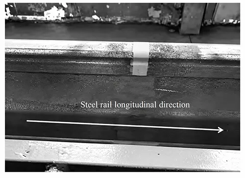
Test Equipment
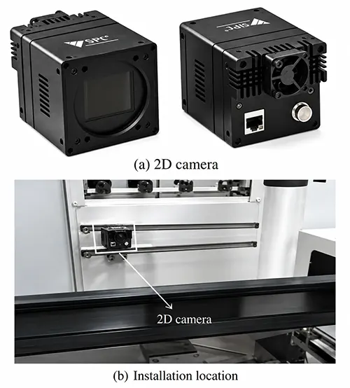
Weld seam localization is performed using an OPT CMOS area-scan camera with a resolution of 5472 × 3648 pixels and a pixel equivalent of 0.2 mm.
A linear LED light source is used to highlight the longitudinal edges and texture of the rail, enabling rapid identification of the weld seam center and calculation of the longitudinal offset, thereby ensuring consistency in the robot’s grinding starting position.
The 2D camera used for weld seam localization and its mounting position are shown in Figure 3.
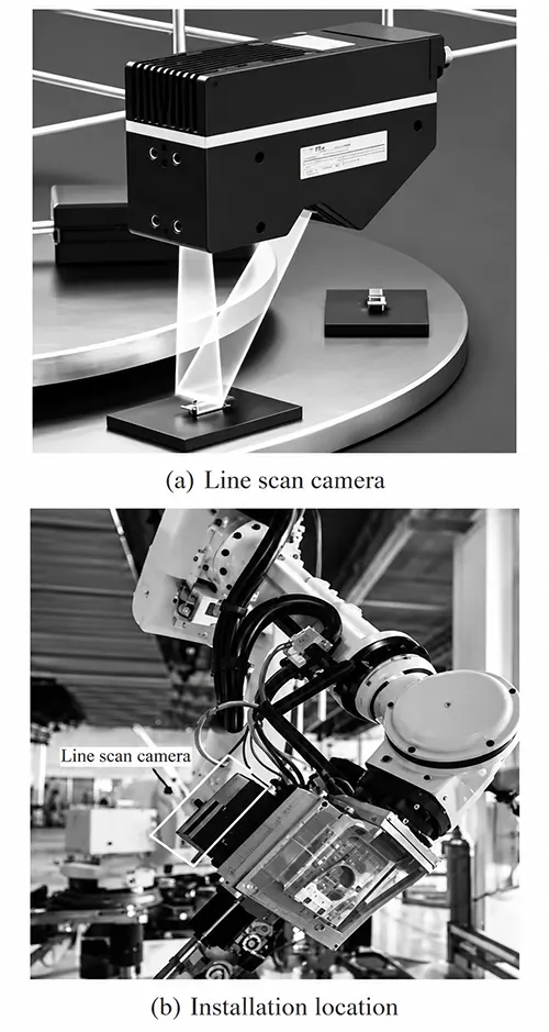
The line-scan camera used for weld bead recognition employs the Youkem 3D line laser measuring instrument AR-8098, which has a vertical repeatability of 2 μm, a measurement range of 100 mm, and an optimal working distance of 145 mm.
The line-scan camera is mounted on the robot flange, and the scanning trajectory program is taught to the robot.
The line-scan camera for weld bead recognition and its mounting position are shown in Figure 4.
Test Method
Specific Test Method:
First, define a reference edge line in a visual photograph of the rail to serve as the calibration benchmark for the theoretical weld centerline.
Next, use a method combining edge detection and spot localization to identify the area where the weld is located after milling;
This area can be accurately identified due to its grayscale values, which differ significantly from the base metal color.
The distance between the reference line and the center of the patch area is calculated;
This distance represents the longitudinal offset of the rail (since the rail is clamped by fixtures in the transverse direction, there is no positional deviation).
This distance is then compared with the theoretical value in the standard template to calculate the difference, and the resulting value is the deviation.
For height detection, 5-mm regions are selected near the left edge, the center, and the right edge, respectively.
After applying a median filter to each region, the average values in the three height directions are obtained.
Using the center average as the reference baseline, the difference between the left and right average values and the center is defined as the height of the weld bead, while the difference between the left and right average values represents the step height of the base metal.
Cross-sectional scans were performed at 22 locations along the rail to verify the height data, as shown in Figure 5. The scanned cross-sections are shown in Figure 6.
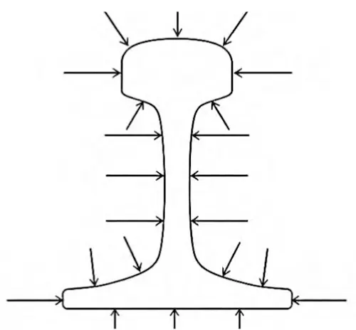
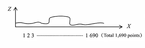
Finally, the grinding process was performed using the adaptive grinding method based on force/position hybrid control proposed in this study, and the weld bead heights before and after grinding were recorded.
Test Results
This study utilized a 2D area-scan camera to identify welds and calculate their positions through patch recognition and deep learning (specifically for cases involving large post-milling areas). The images captured by the 2D camera are shown in Figure 7.
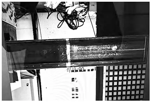
In addition, a line-scan camera was used to capture height data at various locations along the weld.
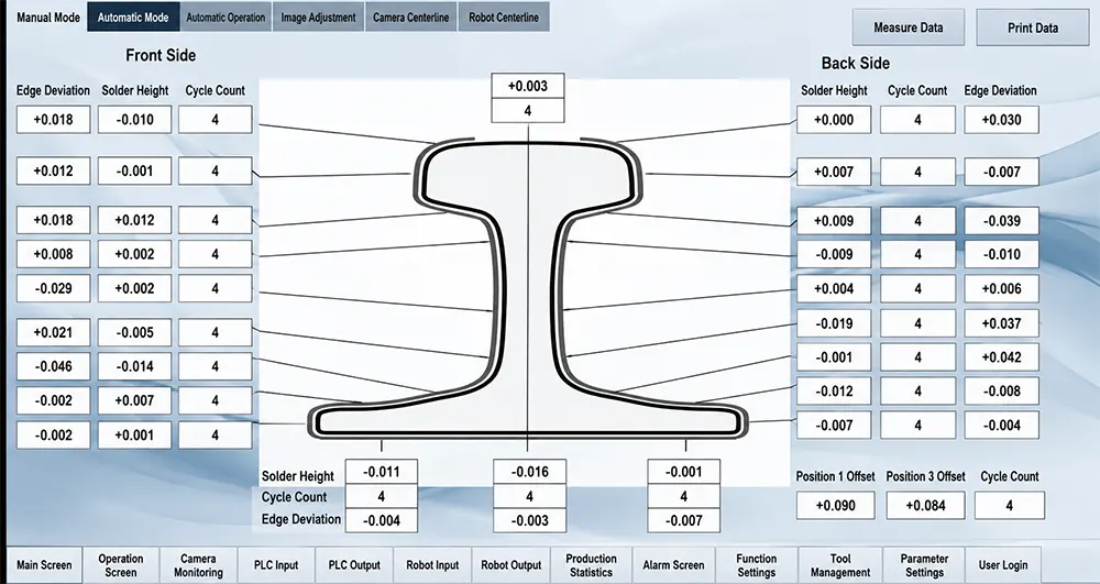
Figure 8 shows the scan data for a single location, while Figure 9 displays the complete height and misalignment data for all 22 locations (the corresponding data was identified and calculated using machine vision and deep learning technologies and displayed in the WinCC interface).
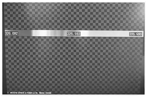
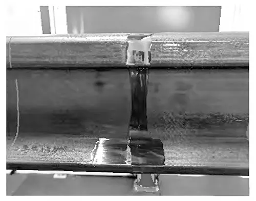
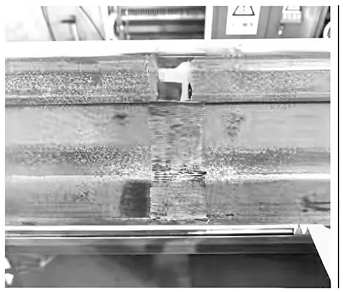
Photographs of the welds before and after grinding by the robotic arm are shown in Figures 10 and 11.
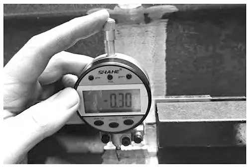
The height of the weld bead after grinding by the robotic arm, as shown in Figure 12, is 0.3 mm, which is less than 0.5 mm and thus meets the requirement in Q/CR 707—2019, “Fixed-Type Rail Flash Butt Welding,” that “the material removal from the base metal during weld bead shaping should be less than 0.5 mm and should not exceed 0.8 mm.”
Conclusion
Currently, the core challenges in weld bead shaping at rail welding facilities center on inconsistent grinding quality and reliance on manual finishing.
The “rough milling machine + robotic arm grinding” method proposed in this study effectively balances shaping efficiency and quality through a collaborative approach of “high-efficiency rough removal and precise fine grinding,” providing rail welding facilities with a novel grinding method.
By integrating machine vision, flexible force/position hybrid control, and adaptive algorithms, this method enables segmented, precise grinding of rail weld beads, driving the development of weld bead shaping technology toward digitalization and intelligence.
Research indicates that the collaborative operation mode of CNC rough milling and robotic arm grinding can achieve high-precision, high-efficiency processing of weld beads, significantly improving the smoothness and consistency of rail welds.