
Turning refers to machining on a lathe, which is a type of mechanical machining.
Lathe machining primarily involves using a turning tool to machine a rotating workpiece.
Lathes are mainly used to machine shafts, discs, sleeves, and other workpieces with rotational surfaces, and they are the most widely used type of machine tool in mechanical manufacturing and repair shops.
There’s no end to what a lathe operator can learn, but even the most basic lathe operator doesn’t need highly advanced skills.
Intruduction
The manufacturing industry commonly classifies lathe operators into five categories in today’s workforce.
1. General Lathe Operators
Simple and easy to learn. Find a lathe shop—you’ll learn more there than you did in school.
2. Mold Lathe Operators
Especially those specializing in precision machining for plastic molds! This requires strict tool selection and precise dimensions.
You need to know which types of steel produce the best finish—that is, a mirror finish.
Is the product made from ABS or some other material? What is the dimensional tolerance of the plastic part in thousandths of a thread?
There’s a lot of common knowledge involved, and modeling clay is an essential tool for this type of lathe operator!!!
To achieve a smooth surface finish that’s easy to polish and reaches a mirror-like effect, you need a foundation in plastic mold making.
Operators commonly use four-jaw chucks and typically machine the workpiece by combining several template plates.
Knowledge of plastic mold threads is essential! This is relatively difficult!
3. Tool Turning
machining reamers, drill bits, and carbide cutting discs. The tool shanks—this type of turning is the simplest, easiest to handle, and most physically demanding.
Production is usually high-volume. The most common methods involve using a two-center setup, turning tapered sections, and adjusting flow rates.
The goal is to work as quickly and simply as possible while minimizing tool wear, because the hardness of the products machined in this process is not much lower than that of your white steel knives!
How well you sharpen your carbide tools directly affects your performance!!
4. Large-Equipment Turners
This type of turning requires advanced technical skills; young workers generally don’t dare to take on these tasks!!
Vertical lathes are frequently used. Example:
When turning a crankshaft, you must first study the blueprints repeatedly to determine the machining sequence—which parts to turn first and which last—whether to allow for grinding allowance or machine directly to dimension, and whether the threads are right-hand or left-hand…These are advanced techniques
5. CNC Lathe Operators
This role is both the simplest and the most difficult. First, you must be able to read drawings, program, apply conversion formulas, and select the right cutting tools!!!
As long as you master the fundamentals of turning and have a solid foundation in math, mechanics, and CAD, you’ll pick it up quickly.
Introduction and Definition
Turning
Turning is a process performed on a lathe that utilizes the rotational motion of the workpiece and the linear or curvilinear motion of the cutting tool to alter the shape and dimensions of a blank, machining it to meet the requirements specified in the drawings.
Turning is a method of machining a workpiece on a lathe by rotating the workpiece relative to the cutting tool.
The workpiece primarily provides the cutting force during turning rather than the cutting tool.
Turning serves as the most basic and common cutting method and plays an important role in production.
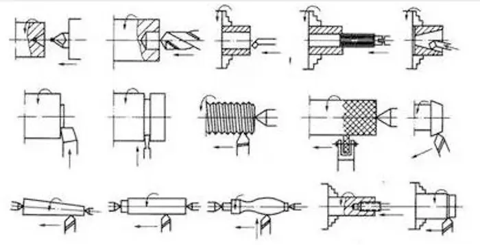
Turning machines can process rotational surfaces, and manufacturers can use turning to machine most workpieces with rotational surfaces, including inner and outer cylindrical surfaces, inner and outer conical surfaces, end faces, grooves, threads, and rotationally formed surfaces.
The primary cutting tool used is the turning tool.
Among all types of metal-cutting machine tools, lathes are the most widely used, accounting for approximately 50% of the total number of machine tools.
Lathes can not only be used to turn workpieces with turning tools but also to perform operations such as drilling, reaming, tapping, and knurling using drills, reamers, taps, and knurling cutters.
Manufacturers classify lathes into horizontal lathes, floor-type lathes, vertical lathes, turret lathes, and copy lathes based on differences in process characteristics, layout, and structural features.
Among these types, horizontal lathes account for the majority.
Safety and Technical Issues
Turning is one of the most widely used machining processes in the machine manufacturing industry.
Given the large number of lathes, the significant workforce involved, the broad scope of machining operations, and the wide variety of tools and fixtures used, safety and technical issues in turning are of particular importance.
The key areas of focus are as follows:
Injuries Caused by Chips and Protective Measures
Steel parts machined on lathes generally have good toughness, and the chips produced during turning are highly ductile and curled, with relatively sharp edges.
During high-speed cutting of steel workpieces, long, red-hot chips are formed that can easily cause injury.
These chips also frequently become entangled in the workpiece, cutting tool, and tool holder.
Therefore, operators should frequently use an iron hook during operation to promptly clear or break these chips.
If necessary, operators should stop the machine before removing them. Under no circumstances should operators use their hands to remove or break chips.
To prevent chip-related injuries, measures such as chip breaking, controlling chip flow direction, and installing various protective shields are commonly adopted.
Chip-breaking measures include grinding chip-breaking grooves or steps onto the turning tool, using appropriate chip breakers, and mechanically clamping the tool.
Workpiece Clamping
During the turning process, improper workpiece clamping causes numerous accidents, including machine tool damage, tool breakage or impact damage, and workpieces falling or flying out and causing injuries.
Therefore, to ensure safe production during turning operations, extra care must be taken when clamping workpieces.
Select appropriate clamping devices for parts of various sizes and shapes; the connection between the chuck—whether a three-jaw or four-jaw chuck, or a specialized clamping device—and the spindle must be secure and reliable.
Operators must center and clamp workpieces tightly; for large workpieces, they may use a sleeve to ensure that the workpieces do not shift, loosen, or eject while rotating at high speeds and under cutting forces.
If necessary, use centers or a center support to reinforce the clamping. Remove the wrench immediately after clamping.
Safe Operation
Before work begins, conduct a thorough inspection of the machine tool and confirm it is in good working order before use.
Operators must ensure that they clamp workpieces and cutting tools in the correct positions and secure them firmly and reliably.
During machining, operators must stop the machine before changing cutting tools, loading or unloading workpieces, or measuring workpieces.
Do not touch a rotating workpiece with your hands or wipe it with a cotton cloth.
Select appropriate cutting speeds, feed rates, and cutting depths; do not operate the machine beyond its rated capacity.
Do not place workpieces, clamping devices, or other debris on the headstock, tool post, or machine bed.
When using a file, move the cutting tool to a safe position, with your right hand in front and your left hand behind to prevent sleeves from getting caught.
A designated person must operate and maintain the machine; other personnel must not operate it.
Points to Note
The machining process for CNC lathes is similar to that of conventional lathes;
However, since CNC lathes complete all turning operations continuously and automatically with a single setup, attention should be paid to the following aspects.
Selecting Appropriate Cutting Parameters
For high-efficiency metal cutting, the workpiece material, cutting tool, and cutting conditions are the three key factors.
These determine machining time, tool life, and machining quality. An economical and efficient machining method necessarily involves the proper selection of cutting conditions.
The three elements of cutting conditions—cutting speed, feed rate, and depth of cut—directly cause tool wear.
As cutting speed increases, the temperature at the tool tip rises, leading to mechanical, chemical, and thermal wear.
A 20% increase in cutting speed reduces tool life by half. The relationship between feed rate and tool rear wear occurs within a very narrow range.
However, a high feed rate increases cutting temperature and results in greater rear wear. Its impact on the tool is less significant than that of cutting speed.
Although the effect of depth of cut on the tool is not as significant as that of cutting speed and feed rate, when machining with very shallow depths of cut, a hardened layer forms on the workpiece material, which similarly affects tool life.
Users must select the appropriate cutting speed based on the material being machined, its hardness, cutting conditions, material type, feed rate, and depth of cut.
Operators determine the most suitable machining conditions based on these factors.
Regular, stable wear leading to the end of tool life is the ideal condition.
However, in actual operations, the selection of tool life is related to tool wear, variations in machined dimensions, surface quality, cutting noise, and machining heat.
When determining machining conditions, it is necessary to conduct research based on actual conditions.
Operators can use coolants or select cutting edges with high rigidity when machining difficult-to-machine materials such as stainless steel and heat-resistant alloys.
Selecting the Right Cutting Tools
(1) For rough turning, select cutting tools with high strength and good durability to meet the requirements of large depth of cut and high feed rates.
(2) For finish turning, select cutting tools with high precision and good durability to ensure the required machining accuracy.
(3) To reduce tool change time and facilitate tool setting, machine-mounted tools and machine-mounted inserts should be used whenever possible.
Selecting Appropriate Fixtures
(1) Whenever possible, use general-purpose fixtures to clamp workpieces and avoid using special-purpose fixtures;
(2) Align the positioning reference points of the parts to minimize positioning errors.
Determining the Machining Path
The machining path refers to the trajectory and direction of the tool’s movement relative to the part during the machining process on a CNC lathe.
(1) The machining path should ensure that machining accuracy and surface roughness requirements are met;
(2) The machining path should be kept as short as possible to minimize tool idle time.
Relationship Between Machining Path and Machining Allowance
Currently, because CNC lathes have not yet been widely adopted, operators should generally machine blanks with excessive machining allowances—especially those with hard forged or cast surface layers—on conventional lathes.
If machining on a CNC lathe is necessary, care must be taken to arrange the program flexibly.
Key Points for Fixture Installation
Currently, manufacturers connect hydraulic chucks and hydraulic clamping cylinders via pull rods.
The key points for clamping a hydraulic chuck are as follows: First, use a wrench to remove the nut on the hydraulic cylinder, remove the pull rod, and pull it out from the rear end of the spindle.
Then, use a wrench to remove the chuck mounting screws, and remove the chuck.
General Guidelines
General Technical Guidelines for Turning (JB/T 9168.2-1998).
Clamping of Turning Tools
1. The shank of a turning tool should not protrude too far from the tool holder; generally, the length should not exceed 1.5 times the height of the shank (except when turning holes, grooves, etc.).
2. The centerline of the turning tool shank should be perpendicular or parallel to the feed direction.
3. Adjustment of the cutting edge height:
(1) When turning end faces, conical surfaces, threads, formed surfaces, or cutting off solid workpieces, the cutting edge should generally be at the same height as the workpiece axis.
(2) When rough-turning outer circles or finish-turning holes, the cutting edge should generally be slightly higher than the workpiece axis.
(3) When turning slender shafts, rough-turning bores, or cutting off hollow workpieces, the cutting edge should generally be slightly lower than the workpiece axis.
4. The bisector of the cutting edge angle of a threading tool should be perpendicular to the workpiece axis.
5. When mounting a turning tool, use only a few flat shims beneath the tool shank, and tighten the clamping screws securely.
Workpiece Clamping
1. When clamping a workpiece in a three-jaw self-centering chuck for rough or finish turning, if the workpiece diameter is less than 30 mm, its overhang should not exceed 5 times the diameter;
If the workpiece diameter is greater than 30 mm, its overhang should not exceed 3 times the diameter.
2. When operators clamp irregularly shaped or unbalanced workpieces using a four-jaw single-action chuck, a faceplate, or an angle iron (bent plate), they must add counterweights.
3. When machining shaft-type workpieces between centers, align the axis of the tailstock center with the axis of the lathe spindle before turning.
4. When machining slender shafts between centers, use a tool rest or a center support.
During machining, operators should pay attention to adjusting the clamping force of the centers and ensure that they properly lubricate the fixed center and center support.
5. When using the tailstock, extend the sleeve as little as possible to reduce vibration.
6. When clamping workpieces with small support surfaces and great height on a vertical lathe, use extended jaws and secure the workpiece with tie rods or clamping plates at appropriate locations.
7. When turning cast or forged parts such as wheels and sleeves, operators should align the workpiece based on the surfaces that they will not machine to ensure uniform wall thickness after machining.
Turning Operations
1. When turning a stepped shaft, operators should generally turn the larger-diameter section first, followed by the smaller-diameter section, to ensure rigidity during machining.
2. Grooves should be cut into the shaft workpiece before finish turning to prevent deformation of the workpiece.
3. When finish-turning a threaded shaft, operators should generally finish-turn the unthreaded section after cutting the threads.
4. Before drilling, operators should turn the end face of the workpiece flat. If necessary, they should drill a center hole first.
5. When drilling deep holes, operators generally drill a pilot hole first.
6. When turning holes with diameters of (Φ10–Φ20) mm, the tool shank diameter should be 0.6–0.7 times the diameter of the hole being machined;
When machining holes larger than Φ20 mm, a tool shank fitted with a tool holder should generally be used.
7. When turning multi-start threads or multi-start worms, a test cut must be performed after adjusting the indexing gears.
8. When using an automatic lathe, adjust the relative position of the tool and workpiece according to the machine’s setup card.
After adjustment, perform a test cut; machining may proceed only after the first piece passes inspection.
During machining, constantly monitor tool wear as well as workpiece dimensions and surface roughness.
9. When turning on a vertical lathe, do not move the cross slide arbitrarily after the tool post has been adjusted.
10. When positional tolerances are required for relevant surfaces of the workpiece, complete the turning operation in a single setup whenever possible.
11. When turning cylindrical gear blanks, the bore and the reference end face must be machined in a single setup.
If necessary, mark lines should be turned near the pitch circle on that end face.
Error Compensation
Modern mechanical manufacturing technology is evolving toward high efficiency, high quality, high precision, high integration, and high intelligence.
Precision and ultra-precision machining technologies have become the most important components and key development directions in modern mechanical manufacturing, and have emerged as critical technologies for enhancing international competitiveness.
With the widespread application of precision machining, turning errors have also become a hot topic of research.
Since thermal errors and geometric errors account for the vast majority of machine tool errors, reducing these two types of errors—particularly thermal errors—has become the primary objective.
Error compensation technology (ECT) has emerged and evolved alongside continuous advancements in science and technology.
The losses caused by thermal deformation of machine tools are considerable.
Therefore, it is imperative to develop high-precision, low-cost thermal error compensation systems that meet actual factory production requirements to correct thermal errors between the spindle (or workpiece) and the cutting tool, thereby improving machine tool machining accuracy, reducing scrap rates, and increasing production efficiency and economic benefits.
Basic Definitions and Characteristics of Error Compensation
1. Basic Definitions
The basic definition of error compensation is to artificially introduce a new error to offset or significantly reduce the original error that is currently causing problems.
By analyzing, statistically evaluating, and inductively determining the characteristics and patterns of the original error, a mathematical model of the error is established.
The goal is to ensure that the magnitude of the artificially introduced error is equal to that of the original error but in the opposite direction, thereby reducing machining errors and improving the dimensional accuracy of parts.
The earliest forms of error compensation were implemented through hardware.
Hardware compensation is a mechanical, fixed-compensation method;
When machine tool errors change, altering the compensation value requires remanufacturing components, recalibrating gauges, or readjusting the compensation mechanism.
Hardware compensation also has the drawbacks of being unable to address random errors and lacking flexibility.
Recently developed software compensation is characterized by its ability to improve machine tool machining accuracy by comprehensively applying advanced technologies from various contemporary disciplines and computer control technology, without making any modifications to the machine tool itself.
Software compensation overcomes many of the difficulties and shortcomings of hardware compensation, propelling compensation technology into a new phase.
2. Characteristics
Error compensation (technology) has two main characteristics: scientific and engineering.
The rapid development of scientific error compensation technology has greatly enriched the theories of precision mechanical design, precision metrology, and precision engineering as a whole, becoming an important branch of this discipline.
Technologies related to error compensation include detection technology, sensor technology, signal processing technology, optoelectronic technology, materials technology, computer technology, and control technology.
As a new branch of technology, error compensation technology has its own distinct content and characteristics.
Further research into error compensation technology to theorize and systematize it will be of great scientific significance.
The engineering significance of error compensation technology is highly significant and encompasses three aspects:
First, the use of error compensation technology can relatively easily achieve levels of precision that would otherwise require substantial costs using “hard technology”;
Second, error compensation technology can address precision levels that “hard technology” typically cannot achieve; and third, when used to meet specific precision requirements, error compensation technology can significantly reduce the manufacturing costs of instruments and equipment, yielding substantial economic benefits.
Causes and Classification of Thermal Errors in Turning
As the precision requirements for machine tools continue to rise, the proportion of thermal errors in total errors will continue to increase, and machine tool thermal deformation has become a major obstacle to improving machining precision.
Machine tool thermal errors are primarily caused by thermal deformation of machine tool components resulting from internal and external heat sources, such as motors, bearings, transmission components, hydraulic systems, ambient temperature, and coolant.
Machine tool geometric errors stem from manufacturing defects, fit errors between components, and dynamic and static displacements of machine tool components, among other factors.
1. Basic Methods of Error Compensation
Based on the above discussion and relevant references, it can be concluded that errors in turning operations are generally caused by the following factors:
Machine tool thermal deformation errors;
Geometric errors in machine tool components and structures;
Errors caused by cutting forces;
Tool wear errors;
other sources of error, such as servo errors in the machine tool’s axis system and errors in CNC interpolation algorithms, etc.
There are two basic methods for improving machine tool accuracy: error prevention and error compensation.
The error prevention method attempts to eliminate or reduce potential sources of error through design and manufacturing processes.
To a certain extent, this method is effective in reducing temperature rise from thermal sources, balancing the temperature field, and minimizing machine tool thermal deformation.
However, it cannot completely eliminate thermal deformation, and the cost is very high;
The application of thermal error compensation, on the other hand, has opened up an effective and economical path to improving machine tool accuracy.
2. Related Conclusions
Research on turning errors is one of the most important components and areas of development in modern mechanical manufacturing, and has become a key technology for enhancing international competitiveness.
Errors arise from multiple factors, and the analysis and study of thermal errors contribute to improving turning accuracy and meeting technical requirements.
Error compensation technology meets the practical production requirements of factories for high precision and low cost.
Thermal error compensation technology can correct thermal drift errors between the spindle (or workpiece) and the cutting tool, thereby improving machine tool machining accuracy, reducing scrap rates, and increasing production efficiency and economic benefits.
Frequently Asked Questions
When using a conventional lathe for heavy-duty turning of threads with large pitches, saddle vibration may sometimes occur.
In mild cases, this causes ripples on the machined surface; in severe cases, it can lead to tool breakage.
Additionally, during cutting operations, students often experience tool binding or breakage.
There are many causes for these issues; here, we will discuss this phenomenon and its solutions primarily by analyzing the forces acting on the cutting tool.
图3
Origin and Causes of the Problem
1. Thread Turning Methods and the Impact of Cutting Force Direction
As we know, when turning threads with a small pitch, the straight-feed cutting method is generally used (making a straight feed perpendicular to the workpiece axis);
When turning threads with a large pitch, the left-right alternating cutting method is often used to reduce cutting forces (by moving the small slide to allow the threading tool to cut with its left and right cutting edges alternately).
When turning threads, the movement of the saddle is achieved by the rotation of the lead screw, which drives the movement of the nut.
There is axial play at the bearings of the lead screw, and there is also axial play between the lead screw and the nut.
2. How Axial Forces Cause Saddle Vibration During Heavy Thread Cutting
When using the alternating-edge cutting method for heavy-duty turning of a right-hand worm with the right-hand cutting edge, the tool bears the force P exerted by the workpiece (neglecting the friction between the chip and the rake face, as shown in Figure 1).
Force P is decomposed into an axial component Px and a radial component Py, where the axial component Px is in the same direction as the tool feed.
the tool transfers this axial component Px to the saddle, thereby causing the saddle to move rapidly and violently back and forth toward the side with clearance.
As a result, the tool oscillates, causing ripples on the machined surface and potentially leading to tool breakage.
However, this phenomenon does not occur when cutting with the left primary cutting edge.
When cutting with the left primary cutting edge, the axial component Px acting on the tool is opposite to the feed direction and moves toward closing the clearance; at this point, the saddle moves at a constant speed.
3. Center Slide Movement and the Risk of Tool Plunging During Lathe Cutting
During cutting, the movement of the center slide is achieved by the rotation of the center slide lead screw, which drives the nut.
There is axial play at the lead screw bearing, and there is also axial play between the lead screw and the nut.
When cutting on a lathe, the tool’s rake face (which has a front angle) bears the force P exerted by the workpiece, (ignoring the friction between the chip and the rake face, as shown in Figure 2).
Force P is decomposed into force Pz and a radial component Pq, where the radial component Pq is in the same direction as the feed direction of the cutting tool, pointing toward the workpiece.
This pushes the tool toward the workpiece, thereby pulling the center slide to move toward the side with clearance, causing the cutting tool to suddenly plunge into the workpiece and resulting in tool breakage or workpiece bending.
Solution
When turning threads with a large pitch using the left-right tool-borrowing method, in addition to adjusting the relevant lathe parameters, you should also adjust the clearance between the saddle and the bed ways to make it slightly tighter.
This increases the friction during movement and reduces the likelihood of the saddle shifting.
However, this clearance should not be set too tight; it should be adjusted so that the saddle can be moved smoothly.
Adjust the clearance of the center slide to be as small as possible;
Adjust the tightness of the small slide to make it slightly tighter to prevent the tool from shifting during turning.
Minimize the protrusion length of the workpiece and tool shank as much as possible, and prioritize cutting with the left cutting edge whenever possible.
When cutting with the right cutting edge, reduce the back depth of cut; increase the rake angle of the right cutting edge, and ensure the cutting edge is straight and sharp to reduce the axial component of force (Px) acting on the tool.
Theoretically, the larger the rake angle of the right cutting edge, the better.
Mnemonic for Turning Tool Edge Grinding
Common types and materials of turning tools, and selection of grinding wheels;
There are five major categories of turning tools, each with different cutting applications,including external cylindrical surfaces, internal bores, and threads, as well as cutting-off and forming operations;
Turning tool edge shapes are divided into three types: straight, curved, and composite;
There are many types of turning tool materials; common ones include carbon steel and aluminum oxide,as well as cemented carbide and silicon carbide; select the grinding wheel based on the material;
Grinding wheel grit is classified by coarseness; do not use coarse and fine grits interchangeably;
Use a coarse grinding wheel for rough turning tools, and a fine grinding wheel for finish turning tools.
Techniques and Precautions for Turning Tool Grinding
Check the equipment before starting the grinder—safety is paramount;
Once the grinding wheel speed is stable, hold the tool with both hands and stand to the side of the wheel;
Keep your elbows tucked against your waist to ensure steady grinding and prevent vibration;
Control the height of the turning tool to keep it centered horizontally on the grinding wheel;
Apply moderate pressure to the grinding wheel—excessive reaction force can cause slippage;
Move the tool evenly by hand; if it becomes too hot to handle, step away temporarily;
Be careful when removing the tool from the grinding wheel; lift it slightly to protect the cutting edge;
High-speed steel tools can be water-cooled to prevent annealing and maintain hardness;
Do not water-quench carbide tools, as sudden cooling can cause them to crack;
Stop grinding before shutting down the machine; turn off the power supply when leaving the machine room.
Steps for Grinding the Cutting Edges of Cylindrical Turning Tools (90°, 75°, 45°, etc.)
For rough grinding, start by grinding the main rake face, with the shank end offset to the left;
Tilt the tool head up 38 degrees to reduce friction at the rake angle;
Next, grind the secondary rake face, and finally the front face;
Grind the front face and front angle simultaneously, following a rough-to-fine sequence;
For fine grinding, start with the front face, then grind the main rake face and secondary rake face;
When grinding the tip radius, hold the front support with your left hand;
Rotate the shank end with your right hand to naturally form the tip radius;
Aim for a flat surface and a straight, stable edge—correct angles are key;
Check carefully with a template and set square; experienced operators can verify by eye.