For small workshops, “one machine, multiple uses” is an essential skill. Today, we’ll explore how to machine polygons on a lathe. Typically, lathes are used for turning rotary surfaces.
However, due to equipment shortages or unbalanced machine loads, technical modifications can enable other (non-turning) operations like polygon machining, grinding, rolling, and thread milling.
Practice demonstrates that adopting tailored technical measures not only requires minimal investment, enables rapid implementation, and yields excellent results—serving as an effective solution to compensate for equipment shortages or mismatches—but also significantly expands the lathe’s application scope. This holds particular relevance for small and medium-sized factories and enterprises.
01 Working Principle of Polygon Machining
To machine polygonal workpieces on a lathe, a specialized device as shown in the figure must be installed.
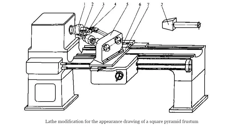
1—Cutter ;disc 2—Workpiece ;3—Chuck;
4—Universal joint ;5—Speed changer ;
6—Screw ;7—Base plate;
During turning, this assembly is mounted on the middle slide, enabling the workpiece and cutting tool to rotate in the same direction.
By utilizing a cutting tool with a specific number of cutting edges and the speed ratio between the tool and workpiece, relative motion between the tool and workpiece is achieved.
This allows the workpiece surface to be formed according to the generating principle, enabling the machining of square, hexagonal, equilateral triangular, trapezoidal, drum-shaped, waist-shaped, flat-shaped, rhombuses, irregular polygons, and tapered polygons.
For example, when machining an equilateral triangle, the gear ratio between the tool and workpiece is i=3. During cutting, the tool tip traces a periodically repeating closed curve relative to the workpiece axis. The enclosed central area forms an approximate triangle.
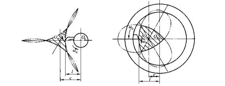
If the workpiece axis lies outside the cutting tool’s circular path, this is termed the “external cutting method,” producing the triangle shown in Figure a;
If the workpiece axis lies inside the cutting tool’s circular path, this is termed the “internal cutting method,” producing the triangle shown in Figure b.
As evident from the triangular configurations, regardless of whether external or internal turning is employed, the surfaces of the triangular workpiece are not flat planes but rather near-flat curved surfaces.
Therefore, the aforementioned polygonal turning method is only suitable for machining where high surface flatness is not required.
Introduction to Widely Used Cutting Tools
The above describes traditional theory. In practical applications, various tool configurations exist, all sharing the same underlying principle.
However, while the theoretical explanation assumes the tool performs the primary motion on the spindle with the workpiece performing auxiliary motion, actual applications often have the workpiece performing the primary motion on the spindle.

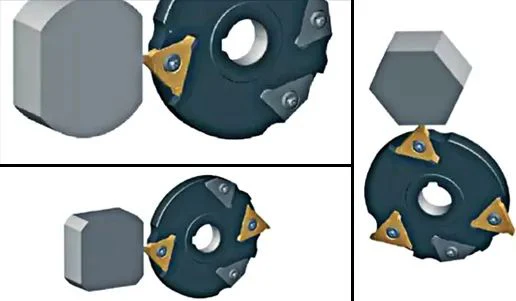
In polygonal turning, a fly cutter disc is used to cut polygons (three to eight sides) on the side surfaces of axially symmetric workpieces.
The workpiece (main spindle) and rotating tool (rotary tool disc) operate in synchronous coupling to machine the contact surface.
The number of cut surfaces depends on the transmission ratio and the number of cutting edges on the tool. The workpiece and tool rotate in opposite directions.
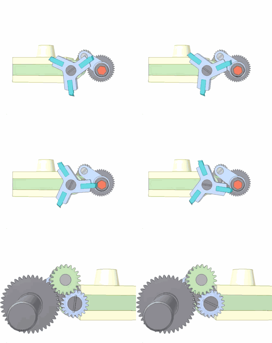
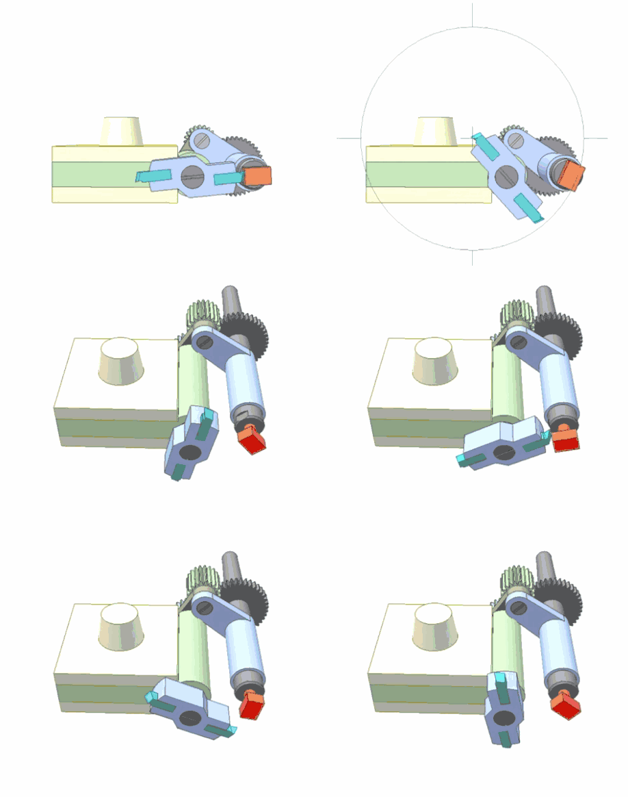
Tools with two cutting edges produce quadrilateral-like shapes, while those with three cutting edges create hexagon-like shapes, etc.
Using different gear ratios or altering the number of cutting edges may cause significant concave or convex deflection arcs on the workpiece surface.
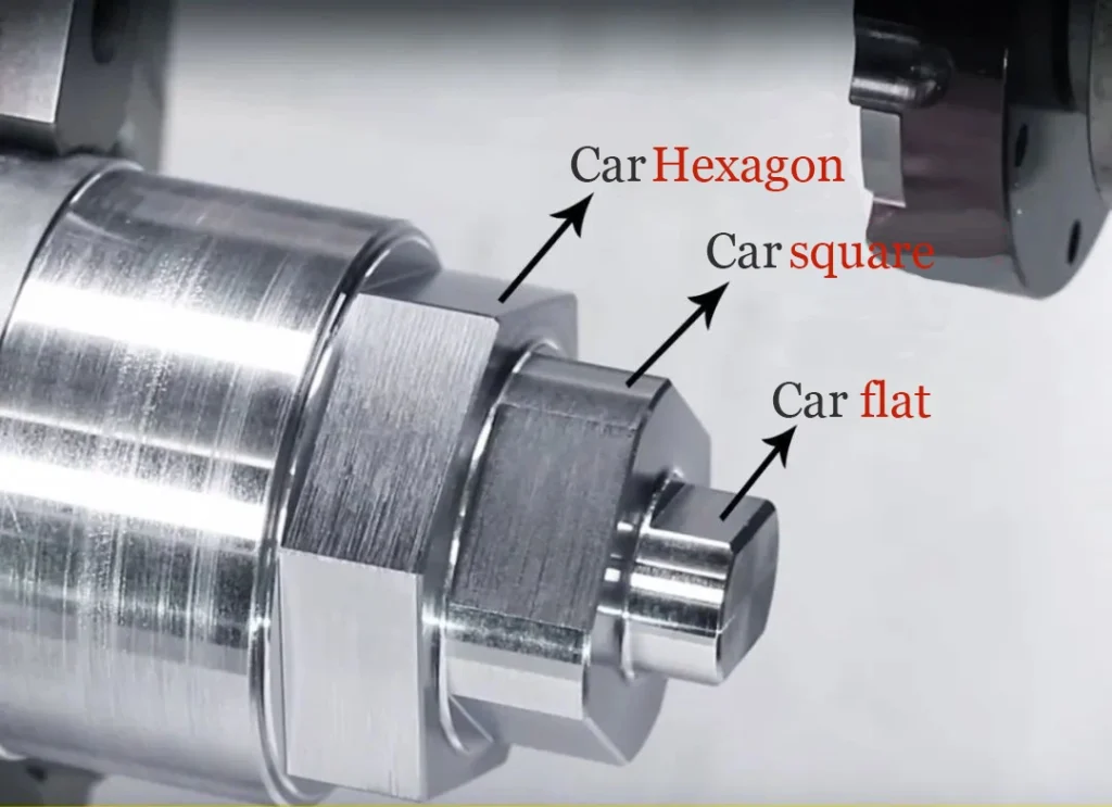
Due to this principle, the contour trajectory generated by the tool tip is precisely an ellipse.
However, the curve projected onto the wrench’s contact surface corresponds to the segment of the ellipse with the larger curvature radius. This does not interfere with assembly operations like tightening or loosening.
Practical Tool Application Case
Finally, let’s observe how to machine polygons on a lathe through a practical demonstration video from tool brand HORN:
