The design requirements for single-piece thin-walled, thin-plate structural components aim to reduce product weight while ensuring structural strength.
This paper investigates and analyzes the milling process of high-precision plastic thin plates.
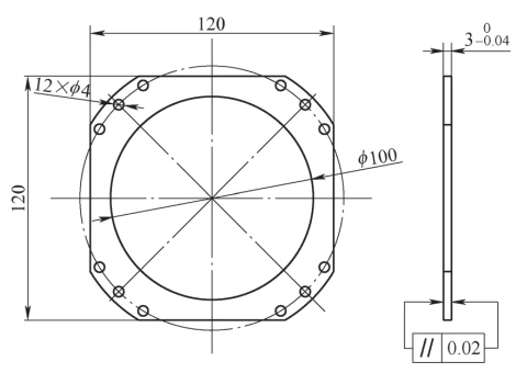
The material of the focusing spacer ring for the objective lens barrel shown in Figure 1 is 2A12-T4 aluminum alloy, with the following technical specifications:
- Part thickness: 3 mm
- Machining allowance: 0.5 mm
- Hole chamfer: 0.3 mm
- Surface roughness Ra: 1.6 μm
Arc-shaped sidewalls and flanges reduce rigidity, making clamping hard and geometric tolerances unstable, ultimately affecting quality.

Analysis of Machining Challenges
Its 3.0 ± 0.04 mm thin wall lacks rigidity and clamping points, causing deformation during machining and making tolerances hard to ensure.
The key to successful machining lies in designing a reasonable process plan and tooling, and selecting the correct clamping method.
Grinding is precise, but the part’s thin plastic surfaces make it unsuitable for this process.
Non-ferrous metals have good plasticity and toughness but low hardness. During grinding, chips and broken grains easily clog the wheel and reduce its cutting performance.
Thin, non-magnetic plates can’t withstand clamping forces, making grinding impractical; only milling is feasible.
Challenges in Milling Processing
Milling the spacer ring is challenging; conventional fixtures often lead to unstable clamping and inconsistent machining quality.
Vise clamping is also unreliable, as parts are prone to deformation during holding, making dimensional tolerances difficult to guarantee.
Clamping plates provide balanced contact but cause deformation and make geometric tolerances hard to maintain during segmented milling.
Clamping Method for Flattening and Counterboring Plastic Thin Plates
- Solution: To control deformation, end-face and hole positioning are employed, with clamping via four peripheral through-holes.
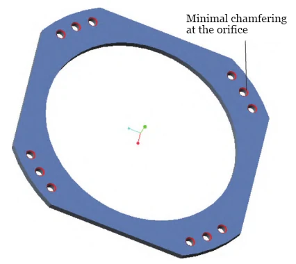
The part’s geometry prevents sufficient clamping from the four through-holes, so a 0.3 mm × 45° chamfer is added for micro-chamfer clamping (Figure 2).

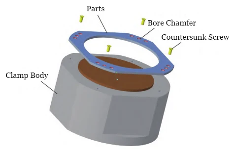
- Technical Principle: As shown in Figure 3, the part’s locating surface contacts the fixture to ensure positioning and dimensional accuracy.
Through-hole clamping uses slight chamfers, with countersunk screws engaging the chamfered edges to secure the part.
The countersunk screw’s embedded face must be smaller than the cutting depth to maintain proper chamfer size.

- Clamping and Machining Steps: Detailed as follows.
Mount the fixture on the machine tool and calibrate the fixture’s locating surfaces using a dial indicator.
Chamfer hole edges 0.3 mm × 45° with allowance (0.05–0.15 mm/pass). For the four peripheral holes, chamfer 0.35–0.40 mm.
Chamfers must be consistent; too small reduces allowance, too large affects spec compliance. For thin walls, reduce cutting depth to prevent deformation.
Clean positioning and mounting surfaces, ensuring only the designated reference points, lines, and surfaces contact the process system.
Mount the part in the core and align the clamping holes. Install the part in the fixture, ensuring alignment and dimensional benchmarks coincide.
Insert screws into the clamping holes and tighten them sequentially.
Perform micro-milling on the machined surfaces.
Remove the workpiece.
Steps 2–7 are repeated with 0.5 mm incremental cuts, gradually reducing and eliminating errors.
Controlling flatness through iterative incremental cutting prevents unnecessary deformation.
Machining Verification
The focusing spacer was milled on an X52K using plastic thin-plate clamping and a φ160 mm right-angle cutter with micro-cutting; parameters are in Table 1.

After repeated micro-cutting, all dimensions met design requirements, with the 3 mm dimension within 0.015 mm and surface parallelism within 0.02 mm.
Conclusion
Plastic parts cannot be clamped with electromagnets, and irregular shapes limit vacuum cup use.
This paper enhances face milling of high-precision plastic sheets via end-face and bore positioning with micro-chamfered holes, meeting dimensional and quality requirements.
